Floor 1, No. 3, Shugang Avenue, Hongmei Town, Dongguan City, Guangdong Province, China

20 years environmental test chamber manufacturer3000+ customer deliverables worldwide           Email: shirley@deruitest.com
WhatsApp Consultation:+86 135 2795 8363

Power Battery Cell Testing System

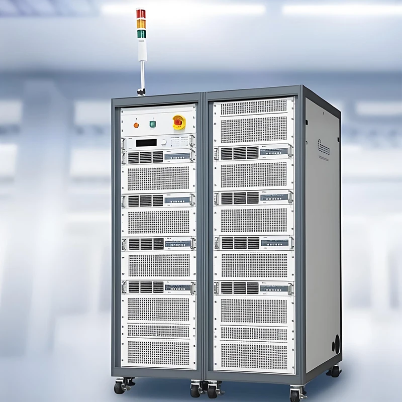
The DERUI DR-D213 power battery cell testing system supports programmable cell charge–discharge, pulse and DCIR workflows. Select the current variant, channels, fixtures and data interfaces around your cell and approved test recipe.

Model DR-D213
Cell Voltage Published 0.8–5 V per channel
Current Variants 30 / 60 / 100 / 150 / 300 A; confirm ordered variant
Accuracy Published voltage/current ±0.02% F.S.; verify conditions
Recording Published 10 ms interval; Excel / TXT export
Before Quotation Confirm channel count, fixtures, recipe, software, site power and FAT
Safe and reliable
well-made
Quality assurance
customization
MessageWhatsApp
Hotline number 15580327593
  • Product Details
  • Technical parameters
  • FAQ
  • Contact us
CELL CHARGE–DISCHARGE & PERFORMANCE TESTING

DR-D213 Power Battery Cell Testing System

Run programmable charge–discharge, pulse and DCIR workflows on battery cells with a configuration selected for the cell, current, channel count and facility. Use the published DR-D213 electrical specification as the starting point, then verify the ordered cabinet, fixtures and software in the technical agreement.

Important distinction: this is an electrical cell-test system. It does not by itself provide a temperature chamber, mechanical abuse rig or certification of a finished battery.
Single-channel voltage0.8–5 V published
Current variants30 / 60 / 100 / 150 / 300 A published
Voltage / current accuracy±0.02% F.S. published
Data interval10 ms published

Start with the Cell and the Test Profile

A useful proposal begins with the cell's voltage window, maximum charge and discharge current, connector design, heat output and required test sequence. Those inputs determine the channel rating, fixture, cabinet quantity and how results will be recorded. DR-D213 is relevant to R&D, cell screening and cycle-performance workflows when the selected configuration matches those inputs.

Performance cycling

Define CC, CV, CCCV, CP or CR steps, end conditions, rest periods and repeat count.

Pulse and DCIR

Provide pulse width, current, SOC points, rest time and the DCIR calculation method.

Production data

Specify channels, traceability fields, export format, uptime and MES requirements before quoting.

Published DR-D213 Electrical Baseline

Parameter Published DR-D213 value Confirm in purchase specification
AC supply 380 ±10% VAC, 50 ±5% Hz; three-phase five-wire Site supply, breaker, earthing and total cabinet input
DC voltage and current 0.8–5 V per channel; 30 / 60 / 100 / 150 / 300 A variants Selected current rating, channel count and parallel operation
Measurement Voltage and current accuracy ±0.02% F.S.; voltage resolution 0.1 mV; current resolution 0.1 mA Range, calibration method, temperature and measurement points
Dynamic response Current response 5 ms (10–90% F.S.); switching 10 ms (−90 to 90% F.S.) Applicable load, method and waveform record
Logging 10 ms recording interval; Excel / TXT export Actual fields, timestamps, retention and export sample
Power feedback Published maximum feedback efficiency ≥75%; power factor >0.99; THD <5% Operating point, grid conditions and witnessed measurement
Environment IP20; 0–40°C working temperature; forced-fan cooling; noise <75 dB Room ventilation, clearances and measurement conditions
Do not carry over the old promotional table: its 0–10 V, 1000 A+, 96–512+ channels and “80%+ energy savings” are not substantiated by the DR-D213 technical parameter tab. Quoted systems may vary; request a model-specific drawing and signed specification.

Workflow and Data: What Is Published, What Needs a Demo

Program the recipe

Published charge modes include CC, CV, CCCV and CP; discharge modes include CC, CV, CP and CR. The page also lists pulse and DCIR workflows.

Protect the test

Published software protections cover over-current, over-voltage, under-voltage, reverse/wrong connection and abnormal communication. Request a fault-response demonstration.

Review the record

Check actual 10 ms data files, timestamps, channel ID, alarms, power interruption behavior and export into your analysis process.

The published software specification lists up to 10,000 editable/program steps and 10 nested-loop layers. These are configuration limits to verify in a live software demonstration, not a promise that every requested test sequence is supported without review.

Select the System Without Mixing It with Other Battery Equipment

Requirement DR-D213 role Separate or project-specific scope
Cell cycling, capacity, pulse, DCIR Electrical source/sink and measurement channels Cell fixture, channel rating, method and software configuration
Temperature-conditioned cycling Published support for linkage with a temperature chamber External chamber, communication protocol, interlocks and profile validation
Mechanical, flame or thermal-abuse tests Not provided by the electrical cycler itself Dedicated abuse equipment and site risk controls
UN 38.3 or product certification May supply electrical data for an applicable program Exact test methods, approved laboratory and complete evidence package

For climatic exposure, review the battery test chamber range as a separate equipment decision.

Acceptance Evidence for Engineering and Procurement

Channel proof

Verify the ordered channel count and current/voltage variant on cabinet labels and wiring diagrams.

Accuracy proof

Agree calibrated instrument, operating points, load and acceptance limits for voltage/current checks.

Workflow proof

Witness charge, discharge, pulse, DCIR, safety trip, interruption recovery and file export.

Ask for real evidence: proposed cabinet photos, fixture drawings, a representative data export, calibration material and a signed FAT checklist. Do not use unapproved customer logos or case-study percentages.

Frequently Asked Questions

What current range does DR-D213 offer?

The published technical table lists 30, 60, 100, 150 and 300 A variants. Confirm the selected variant and its channel count in the quotation.

Is 1000 A standard?

The current DR-D213 technical table does not substantiate a 1000 A variant. Ask DERUI for a separate documented design if that current is required.

Does it include a climatic chamber?

No chamber is established as part of the base electrical system. The published specification mentions linkage with external temperature equipment; confirm hardware and protocol for the project.

Is EIS included?

The legacy marketing copy calls it optional, while the DR-D213 technical parameter table does not specify an EIS module. Treat it as unconfirmed until documented.

Does the equipment itself have UL or UN 38.3 certification?

The present product record does not provide model-specific certificates supporting those claims. Request relevant documents; specimen compliance requires the complete applicable test program.

Request a Cell-Matched DR-D213 Configuration

Send the electrical limits and one representative test recipe. Ask for a channel/cabinet layout, fixture drawing, software demo and measurable FAT plan before approving the proposal.

Request a DR-D213 review

Include with your inquiry

  • Cell format and voltage window
  • Charge/discharge current and channels
  • Pulse/DCIR or cycling recipe
  • Site power, cooling and data interfaces
FacebookLinkedInXRedditWhatsApp

Published DR-D213 baseline. The ordered current variant, channel quantity, accuracy conditions, fixtures and software interfaces require a signed technical agreement.

Item Published specification / confirmation
Model DR-D213
AC wiring / supply Three-phase five-wire; 380 ±10% VAC; 50 ±5% Hz
Power factor / THD >0.99 / <5% (published; test conditions to confirm)
Maximum feedback efficiency ≥75% (published; operating point to confirm)
Single-channel voltage 0.8–5 V
Output-current variants 30 / 60 / 100 / 150 / 300 A; ordered variant and channel count to confirm
Voltage accuracy / resolution ±0.02% F.S. / 0.1 mV
Current accuracy / resolution ±0.02% F.S. / 0.1 mA
Current response / switching 5 ms (10–90% F.S.) / 10 ms (−90 to 90% F.S.)
Data recording interval 10 ms; Excel / TXT export
Charge / discharge modes CC, CV, CCCV, CP / CC, CV, CP, CR
Other modes Rest, pause, condition simulation, pulse, DCIR
Program capacity Up to 10,000 steps and 10 nested-loop layers, as published
Software protection OCP, OVP, UVP, reverse/wrong connection and abnormal-communication protection
External linkage Temperature chamber, MTV/MTS and pressure sensor listed; interface details to confirm
Environment / cooling IP20, 0–40°C, forced-fan cooling
Noise / cabinet dimensions <75 dB; 600 × 850 × 1030 or 600 × 800 × 1980 mm (W × D × H), by configuration

1. What is a Power Battery Cell Testing System?
A Power Battery Cell Testing System is a specialized piece of equipment used to evaluate the performance, longevity, and safety of individual battery cells. It performs critical tests like cycle life, capacity, efficiency, and internal resistance, providing essential data for R&D and quality control in industries like electric vehicles and energy storage.

2. How much does a Power Battery Cell Testing System cost?
The cost varies significantly based on channel count, current/voltage ranges, and features like energy feedback. Entry-level systems can start in the tens of thousands of dollars, while high-channel, high-power systems with full automation can reach several hundred thousand. It's best to request a custom quote based on your specific testing requirements.

3. What is the benefit of an energy feedback (regenerative) system?
An energy feedback system recovers and reuses over 80% of the energy dissipated during charge-discharge cycle testing back to the grid. This drastically reduces electricity costs and heat generation, leading to a faster return on investment and lower operational expenses, especially for high-volume testing labs.

4. Can the testing system handle different battery cell types like prismatic, cylindrical, and pouch?
Yes, a high-quality Power Battery Cell Testing System is designed to be agnostic to cell form factors. With the appropriate fixtures and channel configurations, it can test all common cell types, including 18650, 21700, 4680 cylindrical cells, as well as large-format prismatic and pouch cells.

5. What software is included with the testing system, and what are its capabilities?
These systems typically come with proprietary software (e.g., Derui's BATTEST®). Key capabilities include unlimited test step editing, real-time data graphing and logging, parallel channel control, and advanced data export options (to Excel, SQL, etc.) for in-depth analysis and reporting.

6. Do all channels operate independently?
Yes, in a modern testing system, each channel operates independently. This allows you to run different test profiles on different channels simultaneously, pause individual channels, and handle a mix of cell types or SoC (State of Charge) levels without interrupting other tests, maximizing lab efficiency.

7. What certifications should a reliable Battery Cell Testing System have?
Look for systems that comply with international safety and quality standards. Key certifications include UL and CE for electrical safety, ISO 9001 for quality management, and specific standards like UN38.3 for lithium-ion battery testing compliance.

8. How accurate and stable is the voltage and current control?
For power battery testing, high precision is critical. Top-tier systems offer accuracy better than ±0.05% of Full Scale (FS) and current ripple below 0.05% FS. This ensures that your test results are reliable, repeatable, and can detect subtle performance differences between cells.

9. Can the system integrate with environmental chambers?
Absolutely. Most systems offer interface options (often via CAN or Ethernet) to synchronize with external environmental chambers. This allows you to perform temperature cycling tests, simulating real-world conditions from sub-zero to high temperatures to validate battery performance under stress.

10. What safety features are built into the system?
Beyond standard electrical protections (over-voltage, over-current, short-circuit), advanced systems include software-based alarms, thermal runaway early warning using dV/dt and dT/dt analysis, and seamless integration with facility safety systems to protect both the equipment and operators.

11. What is the typical lead time for delivery and installation?
Lead times can range from 8 to 16 weeks after order confirmation, depending on the system's complexity and customization. This includes manufacturing, factory acceptance testing, and coordination for on-site installation and training by specialized engineers.

12. What kind of support and warranty is provided?
Reputable manufacturers offer a comprehensive warranty (e.g., 24 months) and ongoing support. This often includes remote diagnostics, over-the-air (OTA) software updates, a global spare parts network, and optional on-site installation and training services to ensure your system operates smoothly.


WhatsAppWhatsApp
WhatsAppWhatsApp
WhatsApp
MessageMessage

Request a Quote