Boden 1, Nr. 3, Shugang Avenue, Hongmei Town, Dongguan City, Guangdong Province, China

Hersteller von Umwelttestkammern seit 20 JahrenMehr als 3000 Kunden weltweit geliefert           E-Mail: shirley@deruitest.com
WhatsApp Consultation:+86 135 2795 8363

Strombatteriezelltestsystem

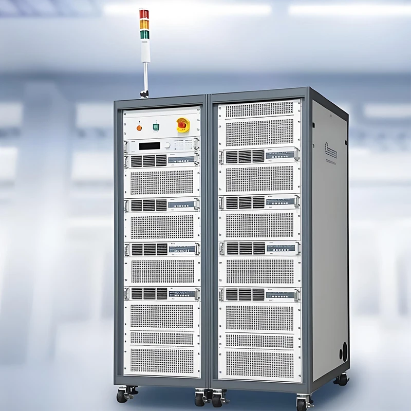
Das DERUI DR-D213 power battery cell testing system supports programmable cell charge–discharge, pulse and DCIR workflows. Select the current variant, channels, fixtures and data interfaces around your cell and approved test recipe.

Modell DR-D213
Cell Voltage Published 0.8–5 V per channel
Current Variants 30 / 60 / 100 / 150 / 300 A; confirm ordered variant
Genauigkeit Published voltage/current ±0.02% F.S.; verify conditions
Recording Published 10 ms interval; Excel / TXT export
Before Quotation Confirm channel count, fixtures, recipe, software, site power and FAT
Sicher und zuverlässig
Hochwertig hergestellt
Qualitätssicherung
Anpassung
NachrichtWhatsApp
Hotline-Nummer 15580327593
  • Produktdetails
  • Technische Parameter
  • FAQ
  • Kontaktieren Sie uns
CELL CHARGE–DISCHARGE & PERFORMANCE TESTING

DR-D213 Power Battery Cell Testing System

Run programmable charge–discharge, pulse and DCIR workflows on battery cells with a configuration selected for the cell, current, channel count and facility. Use the published DR-D213 electrical specification as the starting point, then verify the ordered cabinet, fixtures and software in the technical agreement.

Important distinction: this is an electrical cell-test system. It does not by itself provide a temperature chamber, mechanical abuse rig or certification of a finished battery.
Single-channel voltage0.8–5 V published
Current variants30 / 60 / 100 / 150 / 300 A published
Voltage / current accuracy±0.02% F.S. published
Data interval10 ms published

Start with the Cell and the Test Profile

A useful proposal begins with the cell's voltage window, maximum charge and discharge current, connector design, heat output and required test sequence. Those inputs determine the channel rating, fixture, cabinet quantity and how results will be recorded. DR-D213 is relevant to R&D, cell screening and cycle-performance workflows when the selected configuration matches those inputs.

Performance cycling

Define CC, CV, CCCV, CP or CR steps, end conditions, rest periods and repeat count.

Pulse and DCIR

Provide pulse width, current, SOC points, rest time and the DCIR calculation method.

Production data

Specify channels, traceability fields, export format, uptime and MES requirements before quoting.

Published DR-D213 Electrical Baseline

Parameter Published DR-D213 value Confirm in purchase specification
AC supply 380 ±10% VAC, 50 ±5% Hz; three-phase five-wire Site supply, breaker, earthing and total cabinet input
DC voltage and current 0.8–5 V per channel; 30 / 60 / 100 / 150 / 300 A variants Selected current rating, channel count and parallel operation
Measurement Voltage and current accuracy ±0.02% F.S.; voltage resolution 0.1 mV; current resolution 0.1 mA Range, calibration method, temperature and measurement points
Dynamic response Current response 5 ms (10–90% F.S.); switching 10 ms (−90 to 90% F.S.) Applicable load, method and waveform record
Logging 10 ms recording interval; Excel / TXT export Actual fields, timestamps, retention and export sample
Power feedback Published maximum feedback efficiency ≥75%; power factor >0.99; THD <5% Operating point, grid conditions and witnessed measurement
Environment IP20; 0–40°C working temperature; forced-fan cooling; noise <75 dB Room ventilation, clearances and measurement conditions
Do not carry over the old promotional table: its 0–10 V, 1000 A+, 96–512+ channels and “80%+ energy savings” are not substantiated by the DR-D213 technical parameter tab. Quoted systems may vary; request a model-specific drawing and signed specification.

Workflow and Data: What Is Published, What Needs a Demo

Program the recipe

Published charge modes include CC, CV, CCCV and CP; discharge modes include CC, CV, CP and CR. The page also lists pulse and DCIR workflows.

Protect the test

Published software protections cover over-current, over-voltage, under-voltage, reverse/wrong connection and abnormal communication. Request a fault-response demonstration.

Review the record

Check actual 10 ms data files, timestamps, channel ID, alarms, power interruption behavior and export into your analysis process.

The published software specification lists up to 10,000 editable/program steps and 10 nested-loop layers. These are configuration limits to verify in a live software demonstration, not a promise that every requested test sequence is supported without review.

Select the System Without Mixing It with Other Battery Equipment

Anforderung DR-D213 role Separate or project-specific scope
Cell cycling, capacity, pulse, DCIR Electrical source/sink and measurement channels Cell fixture, channel rating, method and software configuration
Temperature-conditioned cycling Published support for linkage with a temperature chamber External chamber, communication protocol, interlocks and profile validation
Mechanical, flame or thermal-abuse tests Not provided by the electrical cycler itself Dedicated abuse equipment and site risk controls
UN 38.3 or product certification May supply electrical data for an applicable program Exact test methods, approved laboratory and complete evidence package

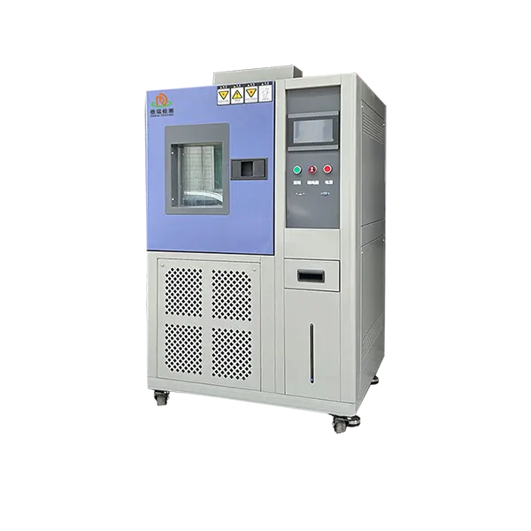
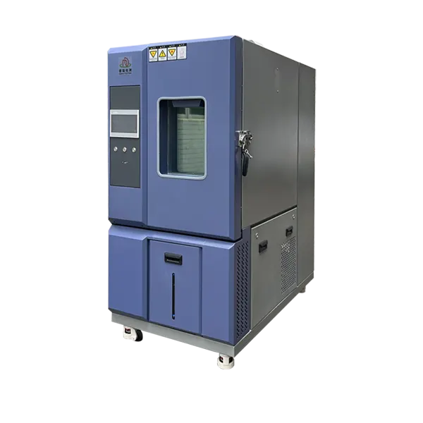
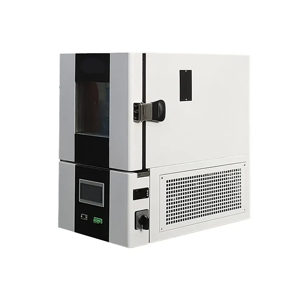
For climatic exposure, review the battery test chamber range as a separate equipment decision.

Acceptance Evidence for Engineering and Procurement

Channel proof

Verify the ordered channel count and current/voltage variant on cabinet labels and wiring diagrams.

Accuracy proof

Agree calibrated instrument, operating points, load and acceptance limits for voltage/current checks.

Workflow proof

Witness charge, discharge, pulse, DCIR, safety trip, interruption recovery and file export.

Ask for real evidence: proposed cabinet photos, fixture drawings, a representative data export, calibration material and a signed FAT checklist. Do not use unapproved customer logos or case-study percentages.

Häufig gestellte Fragen

What current range does DR-D213 offer?

The published technical table lists 30, 60, 100, 150 and 300 A variants. Confirm the selected variant and its channel count in the quotation.

Is 1000 A standard?

The current DR-D213 technical table does not substantiate a 1000 A variant. Ask DERUI for a separate documented design if that current is required.

Does it include a climatic chamber?

No chamber is established as part of the base electrical system. The published specification mentions linkage with external temperature equipment; confirm hardware and protocol for the project.

Is EIS included?

The legacy marketing copy calls it optional, while the DR-D213 technical parameter table does not specify an EIS module. Treat it as unconfirmed until documented.

Does the equipment itself have UL or UN 38.3 certification?

The present product record does not provide model-specific certificates supporting those claims. Request relevant documents; specimen compliance requires the complete applicable test program.

Request a Cell-Matched DR-D213 Configuration

Send the electrical limits and one representative test recipe. Ask for a channel/cabinet layout, fixture drawing, software demo and measurable FAT plan before approving the proposal.

Request a DR-D213 review

Include with your inquiry

  • Cell format and voltage window
  • Charge/discharge current and channels
  • Pulse/DCIR or cycling recipe
  • Site power, cooling and data interfaces
FacebookLinkedInXRedditWhatsApp

Published DR-D213 baseline. The ordered current variant, channel quantity, accuracy conditions, fixtures and software interfaces require a signed technical agreement.

Artikel Published specification / confirmation
Modell DR-D213
AC wiring / supply Three-phase five-wire; 380 ±10% VAC; 50 ±5% Hz
Power factor / THD >0.99 / <5% (published; test conditions to confirm)
Maximum feedback efficiency ≥75% (published; operating point to confirm)
Single-channel voltage 0.8–5 V
Output-current variants 30 / 60 / 100 / 150 / 300 A; ordered variant and channel count to confirm
Voltage accuracy / resolution ±0.02% F.S. / 0.1 mV
Current accuracy / resolution ±0.02% F.S. / 0.1 mA
Current response / switching 5 ms (10–90% F.S.) / 10 ms (−90 to 90% F.S.)
Datenaufzeichnungsintervall 10 ms; Excel / TXT export
Charge / discharge modes CC, CV, CCCV, CP / CC, CV, CP, CR
Other modes Rest, pause, condition simulation, pulse, DCIR
Program capacity Up to 10,000 steps and 10 nested-loop layers, as published
Softwareschutz OCP, OVP, UVP, reverse/wrong connection and abnormal-communication protection
External linkage Temperature chamber, MTV/MTS and pressure sensor listed; interface details to confirm
Environment / cooling IP20, 0–40°C, forced-fan cooling
Noise / cabinet dimensions <75 dB; 600 × 850 × 1030 or 600 × 800 × 1980 mm (W × D × H), by configuration

1. Was ist ein Power-Batteriezellen-Testsystem?
Ein Power-Batteriezellen-Testsystem ist ein spezielles Gerät, das verwendet wird, um die Leistung, Langlebigkeit und Sicherheit einzelner Batteriezellen zu bewerten. Es führt wichtige Tests wie Zykluslebensdauer, Kapazität, Effizienz und Innenwiderstand durch und liefert essentielle Daten für Forschung und Entwicklung sowie Qualitätskontrolle in Branchen wie Elektrofahrzeugen und Energiespeicherung.

2. Wie viel kostet ein Power-Batteriezellen-Testsystem?
Die Kosten variieren erheblich je nach Kanalanzahl, Strom-/Spannungsbereichen und Funktionen wie Energie-Rückführung. Einstiegsmodelle können bei Zehntausenden von Euro beginnen, während hochkanalige, leistungsstarke Systeme mit vollständiger Automatisierung mehrere Hunderttausend erreichen können. Es ist am besten, ein individuelles Angebot basierend auf Ihren spezifischen Testanforderungen anzufordern.

3. Was ist der Vorteil eines Energie-Rückführungssystems (regenerativ)?
Ein Energie-Rückführungssystem gewinnt über 80 % der während des Lade-Entlade-Zyklus-Tests dissipierten Energie zurück und speist sie wieder ins Netz ein. Dies reduziert die Stromkosten und die Wärmeentwicklung erheblich, was zu einer schnelleren Amortisation und niedrigeren Betriebskosten führt, insbesondere für Hochvolumen-Testlabore.

4. Kann das Testsystem verschiedene Batteriezelltypen wie prismatisch, zylindrisch und Beutelzellen handhaben?
Ja, ein hochwertiges Power-Batteriezellen-Testsystem ist so konzipiert, dass es unabhängig von der Zellform ist. Mit den entsprechenden Halterungen und Kanal-Konfigurationen kann es alle gängigen Zelltypen testen, einschließlich 18650, 21700, 4680 Zylinderzellen sowie großformatige prismatische und Beutelzellen.

5. Welche Software ist im Testsystem enthalten und welche Funktionen bietet sie?
Diese Systeme werden typischerweise mit proprietärer Software (z.B. Deruis BATTEST®) geliefert. Zu den wichtigsten Funktionen gehören unbegrenzte Testschrittbearbeitung, Echtzeit-Datenvisualisierung und -protokollierung, parallele Kanalsteuerung und erweiterte Datenexportoptionen (z.B. nach Excel, SQL) für detaillierte Analysen und Berichte.

6. Arbeiten alle Kanäle unabhängig voneinander?
Ja, in einem modernen Testsystem arbeitet jeder Kanal unabhängig. Dadurch können Sie verschiedene Testprofile gleichzeitig auf unterschiedlichen Kanälen durchführen, einzelne Kanäle pausieren und eine Mischung aus Zelltypen oder SoC (Ladezustand) verwalten, ohne andere Tests zu unterbrechen, was die Laboreffizienz maximiert.

7. Welche Zertifizierungen sollte ein zuverlässiges Batteriezellen-Testsystem haben?
Achten Sie auf Systeme, die internationalen Sicherheits- und Qualitätsstandards entsprechen. Wichtige Zertifizierungen umfassen UL und CE für elektrische Sicherheit, ISO 9001 für Qualitätsmanagement, und spezifische Standards wie UN38.3 für die Einhaltung der Vorschriften für Lithium-Ionen-Batterietests.

8. Wie genau und stabil sind die Spannungs- und Stromsteuerung?
Für Tests von Leistungsspeicherbatterien ist hohe Präzision entscheidend. Spitzen-Systeme bieten eine Genauigkeit besser als ±0,05% des Nennwerts (FS) und einen Stromwelligkeit unter 0,05% FS. Dies stellt sicher, dass Ihre Testergebnisse zuverlässig, reproduzierbar sind und subtile Leistungsunterschiede zwischen Zellen erkennen können.

9. Kann das System mit Umweltschränken integriert werden?
Absolut. Die meisten Systeme bieten Schnittstellenoptionen (oft über CAN oder Ethernet), um mit externen Umweltschränken zu synchronisieren. Dadurch können Temperaturzyklen getestet werden, die reale Bedingungen von sub-zero bis hohen Temperaturen simulieren, um die Batterieleistung unter Stress zu validieren.

10. Welche Sicherheitsmerkmale sind im System integriert?
Neben standardmäßigen elektrischen Schutzmaßnahmen (Überspannung, Überstrom, Kurzschluss) umfassen fortschrittliche Systeme softwarebasierte Alarme, Frühwarnungen bei thermischem Durchgehen mittels dV/dt- und dT/dt-Analysen sowie nahtlose Integration in die Sicherheitssysteme der Einrichtung, um sowohl die Ausrüstung als auch die Bediener zu schützen.

11. Wie lang ist die typische Liefer- und Installationszeit?
Die Lieferzeiten können je nach Komplexität und Anpassung des Systems zwischen 8 und 16 Wochen nach Auftragsbestätigung liegen. Dies umfasst die Herstellung, die Werkabnahmeprüfung sowie die Koordination für die Vor-Ort-Installation und Schulung durch spezialisierte Ingenieure.

12. Welche Unterstützung und Garantie werden angeboten?
Renommierte Hersteller bieten eine umfassende Garantie (z.B. 24 Monate) und laufenden Support. Dies umfasst Fern-Diagnosen, Software-Updates Over-the-Air (OTA), ein globales Ersatzteilnetzwerk sowie optionale Vor-Ort-Installations- und Schulungsdienste, um einen reibungslosen Betrieb Ihres Systems zu gewährleisten.


WhatsAppWhatsApp
WhatsAppWhatsApp
WhatsApp
NachrichtNachricht

Anfrage für ein Angebot