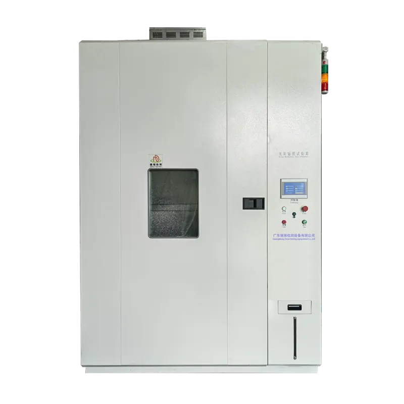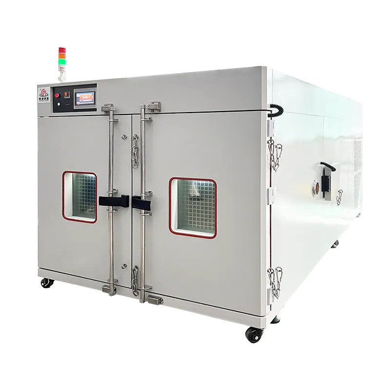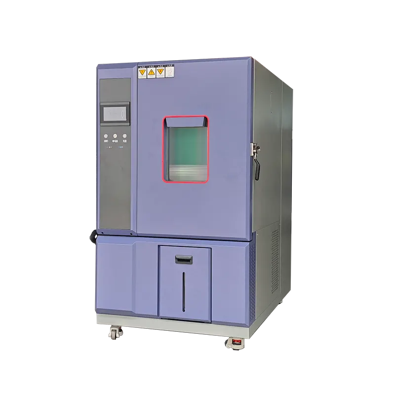


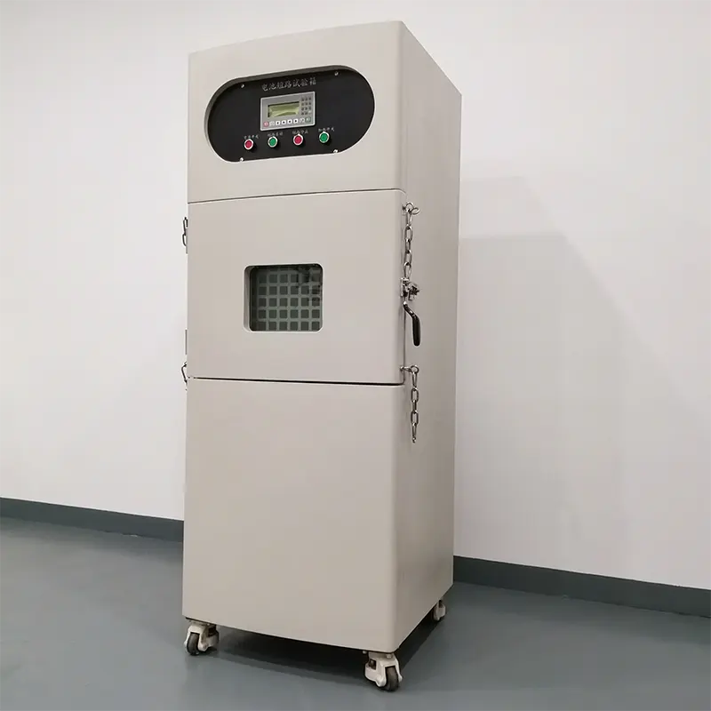

DR-H204 Rapid Temperature Change Test Chamber
Run accelerated heating and cooling cycles for environmental stress screening of electronics, automotive components, aerospace assemblies and other temperature-sensitive products. The published 800 L configuration provides selectable low-temperature options and rapid cooling rates up to 25°C/min.
Where Fast-Rate Thermal Cycling Fits
This chamber keeps the specimen stationary while the conditioned air follows a programmed ramp and dwell profile. It is designed for screening and thermal cycling—not the near-instant transfer exposure produced by a two- or three-zone thermal shock chamber.
Electronics and semiconductors
Expose boards, modules, connectors and power electronics to repeated temperature transitions that help reveal assembly and material weaknesses.
Automotive and aerospace
Cycle controllers, sensors, lighting, avionics and compact assemblies using the applicable product or customer procedure.
Battery and energy systems
Evaluate non-abuse thermal-cycle performance only after specimen heat, electrical interfaces and the required safety scope are defined.
Published DR-H204 800L Configuration
| Item | Published value | Procurement note |
|---|---|---|
| Internal workspace | 1000 × 800 × 1000 mm; 800 L | Confirm W × D × H and usable space after fixtures and airflow clearance. |
| External dimensions | 1580 × 1700 × 2260 mm | Confirm installation, service and door-access clearances on the drawing. |
| Temperature range options | -20 / -40 / -70°C to +150°C | Select one refrigeration configuration for the required profile. |
| Temperature fluctuation | ±1°C | Confirm setpoint, stabilized condition, sensor location and load. |
| Heating rate | 5°C/min | Confirm average or linear definition, temperature span and load state. |
| Cooling rate options | 5 / 10 / 15 / 25°C/min | Confirm selected rate, temperature span, ambient, cooling utility and load. |
| Sample trays and port | Three SUS304 trays; Φ50 mm test hole | Confirm tray loading and whether port size/quantity suits the interfaces. |
| Power supply | Three-phase 380 V / 50 Hz | Rated current and power depend on the final refrigeration configuration. |
Define the Ramp Before the Chamber Is Sized
Fix the endpoints
State the exact start and finish temperatures. A rate quoted across a narrow central span cannot be assumed across the full chamber range.
Choose the measurement basis
Specify chamber-air control, monitoring sensor positions and whether specimen temperature must follow the same slope.
Add the real load
Include specimen mass, fixture thermal mass, powered watts, duty cycle and cable heat leakage in the cooling calculation.
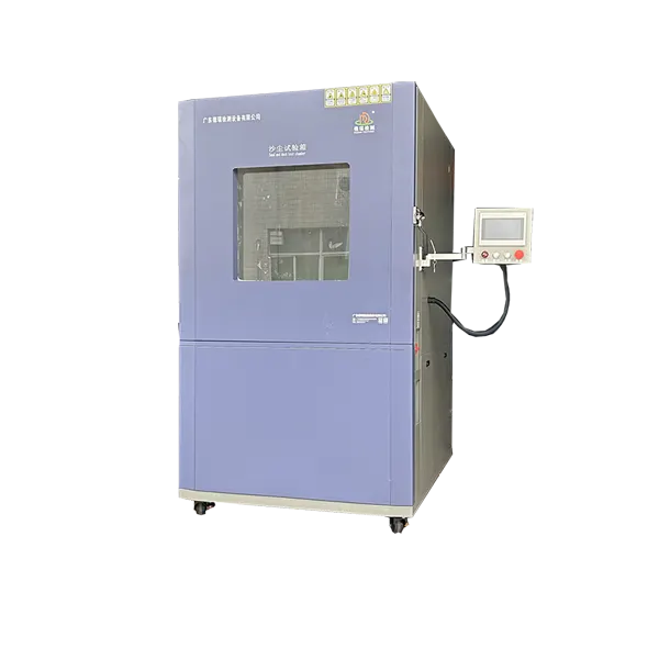
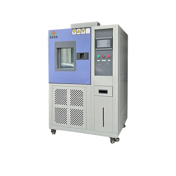
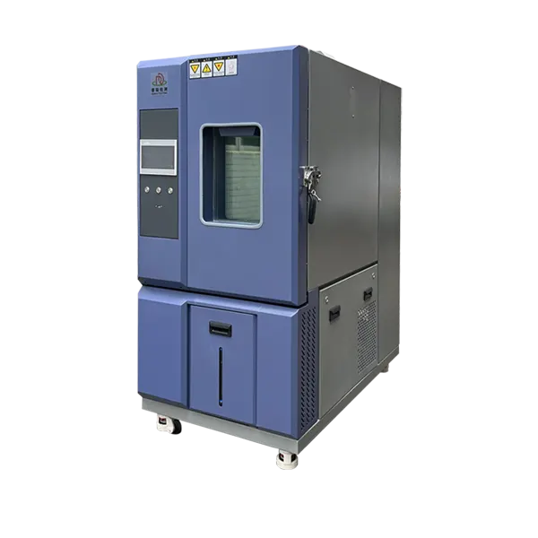
Rapid Thermal Cycling Chamber Reference Image
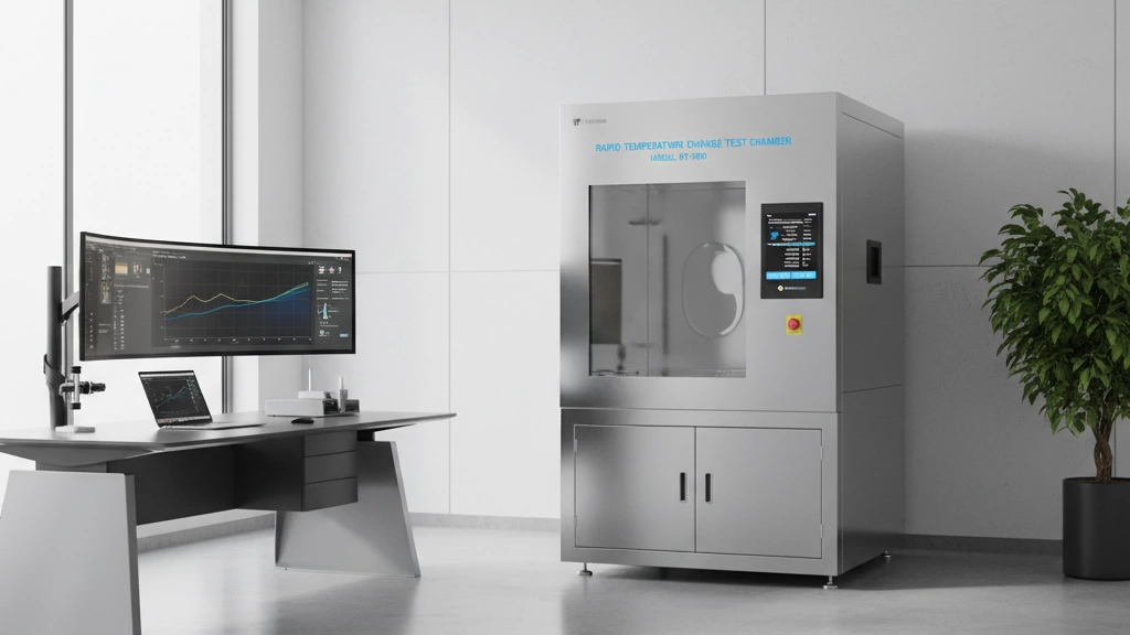
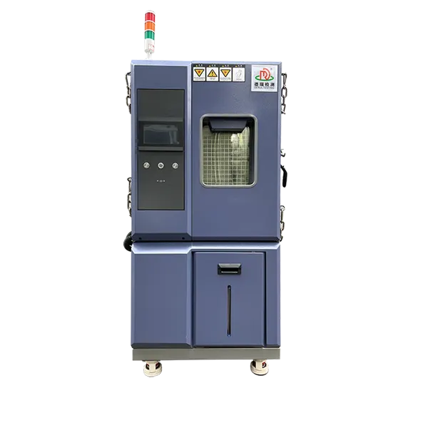
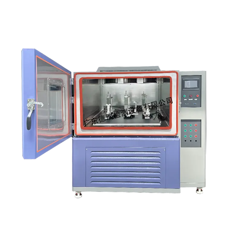
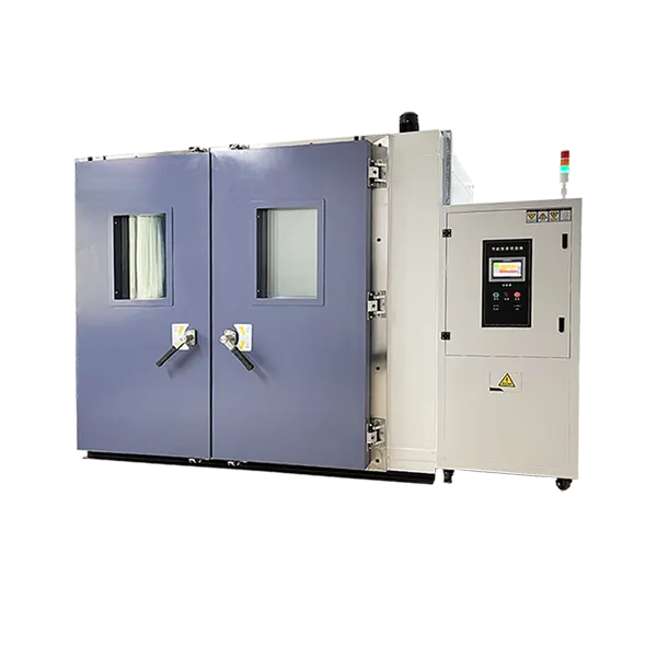
Current DERUI rapid temperature change chamber reference image. Final door, controller, ports and refrigeration arrangement follow the approved configuration.
Engineering Factors That Control Loaded Performance
Refrigeration capacity
The selected low-temperature end, cooling rate, test load and facility cooling conditions determine the required refrigeration system.
Heating and control
Heater capacity and control tuning must reproduce the programmed upward transition without unacceptable overshoot.
Airflow and fixture design
Specimen spacing and low-mass, open fixtures help conditioned air reach all surfaces and reduce local temperature lag.
Powered heat
Live electronics oppose the cooling system. Provide maximum continuous and transient watts rather than a nominal device rating.
Ports and interfaces
Define power, signals, thermocouples and communication cables so feedthroughs can be sized and sealed correctly.
Facility utilities
Confirm electrical supply, heat rejection, cooling-water conditions if applicable, drainage, ambient limits and service access.
Rapid Change Chamber vs. Thermal Shock Chamber
| Selection point | Rapid temperature change chamber | Thermal shock chamber |
|---|---|---|
| Specimen movement | Remains stationary in one workspace. | Typically transfers between separate hot and cold zones. |
| Exposure definition | Controlled air ramp in °C/min with programmed dwells. | Transfer time and recovery after zone change are central. |
| Powered monitoring | Well suited when interfaces remain connected during cycling. | Requires cable routing compatible with the transfer system. |
| Use when | The procedure specifies a controlled temperature-change rate. | The procedure requires abrupt zone transfer or thermal shock recovery. |
Map the Chamber to the Test Method
The standard defines the exposure; the equipment does not create compliance by itself. Confirm the current edition, severity, test type and acceptance criteria.
| Reference | Typical relationship | Confirm before claiming suitability |
|---|---|---|
| IEC 60068-2-14 | Change of temperature methods | Test designation, temperatures, transition, dwell and specimen operation. |
| MIL-STD-810H | Tailored high/low temperature exposure | Applicable method/procedure, rates, stabilization and functional checks. |
| JEDEC device methods | Electronic component temperature cycling | Exact JESD method, air profile, load, monitoring and lot acceptance. |
| Customer ESS profile | Production screening | Fault-detection goal, cycle count, test limits and data retention. |
RFQ and FAT Checklist
| Topic | Information to provide or verify |
|---|---|
| Profile | Start/end temperatures, rate definition, dwells, cycles and tolerances. |
| Specimen | Envelope, mass, quantity, material, fixtures and powered heat. |
| Measurement | Air/specimen sensors, sample rate, rate calculation and report format. |
| Interfaces | Power, signals, thermocouples, network, test ports and safety interlocks. |
| Utilities | Voltage, phase, current, cooling water if required, ambient and heat rejection. |
| FAT | Empty/loaded condition, sensor map, ramps, dwells, alarms and acceptance limits. |
Frequently Asked Questions
What ramp rates are published for this DR-H204 page?
The current technical table lists 5°C/min heating and 5, 10, 15 or 25°C/min cooling. Confirm the selected rate, temperature span and whether it is average or linear in the quotation.
Does the published rate apply under full powered load?
The visible table does not establish one universal loaded guarantee. Provide fixture mass and maximum powered heat so loaded performance can be calculated and included in FAT criteria.
Is this the same as a thermal shock chamber?
No. A rapid change chamber controls a programmed air-temperature ramp while the specimen remains stationary. A thermal shock chamber typically transfers the specimen between separate zones.
Is humidity standard on the 800 L configuration?
The page discusses optional humidity, but the published 800 L technical table does not establish a confirmed humidity envelope for every rapid-rate configuration. Treat it as an option requiring a separate operating chart.
What power supply is published?
The current 800 L technical table states three-phase 380 V / 50 Hz. Final current and rated power depend on the selected temperature and ramp-rate configuration.
What should I send for a quotation?
Send the full profile, rate definition, specimen drawing and mass, fixture, powered heat, interfaces, facility utilities, standards and FAT requirements.
Configure the DR-H204 from the Loaded ESS Profile
Send the complete temperature cycle and specimen data. DERUI can confirm the low-temperature option, cooling rate, refrigeration capacity, interfaces, utilities and acceptance plan before quotation.