
800 L SALT FOG · BATCH LOADING · TRACEABLE EXPOSURE
More Horizontal Loading Space for Your Corrosion-Test Batch
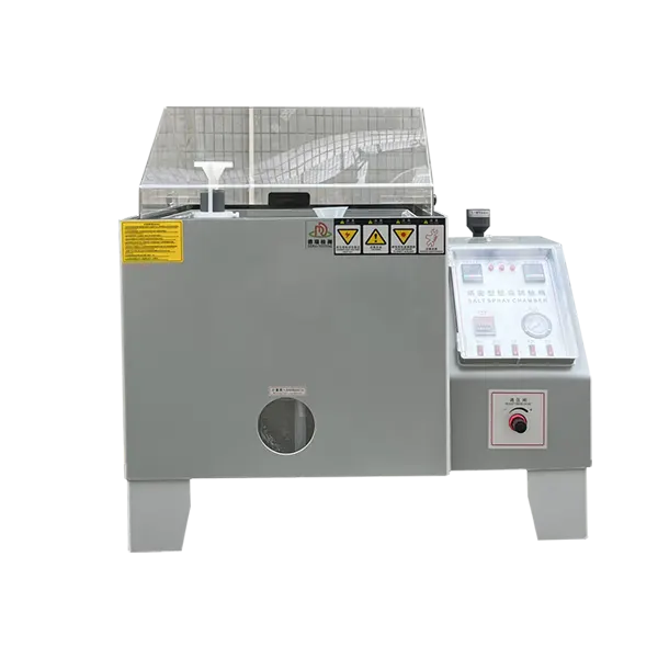
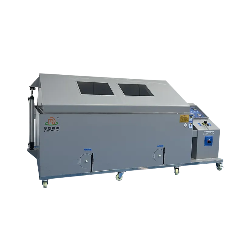
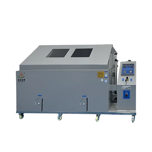
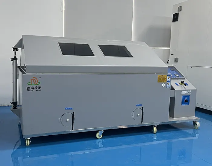
The DERUI DR-H304-160 800L salt fog test chamber provides a 1600 × 1000 × 500 mm enclosure for multiple coated specimens, component sets and fixtures. Continuous or periodic spray operation supports a defined exposure programme, with the loading arrangement chosen around the parts and required fog checks.
1600 mm internal width
A wider loading envelope than the 1200 mm-wide DR-H304-120.
800 L nominal volume
Geometric capacity—not a guaranteed specimen count.
40 L solution tank
Plan inspection and replenishment for the intended exposure.
Use the additional width to plan a complete batch layout rather than crowd more pieces into a smaller cabinet. Send specimen dimensions, quantity and fixture drawings to review whether this model fits your laboratory workload.
What the 160 Configuration Adds to Your Loading Plan
“160” identifies this model’s 1600 mm internal width; it does not mean 160 L. Compared with the 600 L DR-H304-120, the DR-H304-160 adds 400 mm of width while retaining the same listed 1000 mm depth and 500 mm height.
That extra width can accommodate a wider fixture envelope or additional specimen positions when spacing and deposition remain suitable. It does not automatically add another rack level, more vertical clearance or a fixed percentage increase in sample throughput.
Plan the Batch Before You Count the Samples
Repeated production checks benefit from a loading arrangement that can be reproduced between runs. Decide which specimens belong in the same exposure and how each will be identified, mounted and inspected. Keep the required method and inspection schedule compatible across the batch.
| Batch arrangement | Information to provide | Loading issue to review |
|---|---|---|
| Repeated coated panels | Panel dimensions, quantity, exposed face and required angle | Neighboring panels must not shield each other or receive runoff from another specimen. |
| Small components on fixtures | Fixture drawing, part spacing, contact points and total mass | Fixture materials, unintended contact and collector access can affect the exposure. |
| Matched production lots | Lot identifiers, specimen selection and common preparation | Maintain comparable geometry and conditions; record the lot and position for each result. |
| Larger formed parts or enclosures | Overall envelope, recesses, orientation and drainage | Include the complete fixture and verify exposure of the surfaces being evaluated. |
Mixing unrelated specimens simply because they fit can make a run harder to interpret. Different methods, exposure durations or handling rules may require separate runs. Follow the prescribed layout and any permitted position-change schedule; do not move specimens midway without recording it.
A practical loading submission
Send a top and side view showing part and fixture dimensions, specimen positions, exposed surfaces and intended collector locations. Include the total mass and any access needed for inspection. DERUI can review the envelope and support arrangement against the proposed test configuration.
Keep Fog Checks Visible Across the Loaded Cabinet
More specimen positions make the exposure layout more important. Avoid direct atomizer impingement, shielding and runoff into collection vessels. Place collectors and assess readings using the adopted method instead of assuming that a pressure display proves acceptable fog deposition.
Record collectors individually
Identify collector area, position, collection time and volume. Do not hide a low reading and a high reading in one favorable average.
Assess the loaded arrangement
Agree the representative specimen/fixture layout for verification. Check whether fixtures interfere with fog or collection.
Retain the operating context
Keep temperature, solution checks, air conditions and access events with the run record. Investigate changes instead of silently adjusting settings.
Solution preparation and collected-fog verification are separate checks. Evaporation and operating conditions can affect the collected solution. Use the prescribed measurement basis and conditions, and keep both records where required.
The Q-Lab fog-collection explanation provides background on distribution and chemistry. Q-FOG pressure or pump settings are not settings for the DR-H304-160; use this chamber’s operating instructions and your required procedure.
Construction and Spray Operation
PVC cabinet
The listed 8 mm rigid PVC construction is suited to the cabinet’s salt fog environment. Include the intended test chemistry when specifying compatibility.
Inclined specimen supports
Glass-fiber rods and V-shaped supports provide mounting positions for suitable specimens. Choose the required angle from the procedure rather than apply one angle to every part.
Continuous / periodic spray
Select the specified spray sequence for the programme. Timed spray-off periods do not establish controlled humidity or drying capability.
For longer exposures, plan access to solution supply, collectors, drainage and service points. Request the configuration-specific filling and maintenance instructions, including any automatic replenishment functions you require, in the equipment proposal.
Inspect the nozzle and solution path according to the maintenance procedure. Salt crystallization, changes in supply conditions or contamination should be addressed before they undermine the exposure; no cabinet should be described as permanently clog-free.
800L Salt Fog Chamber Specifications
The DR-H304-160 has a 1600 mm-wide enclosure and 800 L nominal volume. Operating settings below describe the equipment configuration, not a complete test recipe. Agree the required method, measurement locations and loading conditions for acceptance.
| Specification | DR-H304-160 configuration |
|---|---|
| Model | DR-H304-160 |
| Nominal volume | 800 L geometric volume; specimen capacity depends on the loading layout |
| Internal dimensions (W × D × H) | 1600 × 1000 × 500 mm |
| External dimensions (W × D × H) | 2300 × 1300 × 1400 mm; allow additional cover movement, service and connection clearance |
| Cabinet material | 8 mm rigid PVC plate |
| Specimen supports | 10 mm glass-fiber rods and V-shaped supports for approximately 15° or 30° placement; select orientation from the procedure |
| Temperature range | Room temperature to 55°C |
| Temperature fluctuation | ≤ ±0.5°C |
| Temperature uniformity | ≤ ±2°C |
| Temperature indication accuracy | ±1°C |
| Spray modes | Continuous and periodic spray |
| NSS cabinet operating setting | 35 ±1°C in the listed configuration |
| CASS cabinet operating setting | 50 ±1°C in the listed configuration; specify chemistry compatibility and the required method before ordering |
| Saturated-air barrel settings | 47 ±1°C for the listed NSS configuration; 63 ±1°C for the listed CASS configuration |
| Solution tank | 40 L |
| Fog collection rate | 1.0–2.0 mL per 80 cm² per hour; collector positions and measurement interval follow the selected method |
| Air source | Buyer-provided 1 HP compressor in the listed configuration; required delivery, pressure and air treatment to be specified |
| Protection functions | Electrical leakage, overpressure, overtemperature and overload fuse protection |
| Accessories | Test salt, collection/measuring vessel and spray nozzle set; specify quantities in the quotation |
Temperature fluctuation, uniformity and indication accuracy are different specifications. Fog deposition and method-required cabinet verification must be checked separately. The room-temperature lower limit does not indicate active cooling.
Choose the Method Separately from the Capacity
A larger enclosure does not change the required chemistry or acceptance criteria. State the standard and edition, the selected exposure, specimen preparation, duration and evaluation endpoint before ordering.
| Exposure requirement | Equipment decision |
|---|---|
| ASTM B117 or ISO 9227 NSS programme | Define apparatus operation, specimen layout, fog checks and product-specific evaluation. |
| AASS or CASS requirement | Specify the chemistry, operating conditions, compatible solution system and contamination-control procedure. |
| Multi-stage cyclic corrosion | Specify all humidity, drying, application and transition requirements; assess equipment capability for the complete sequence. |
The ISO 9227 scope distinguishes NSS, AASS and CASS and includes cabinet-corrosivity evaluation. It does not assign one duration or acceptance rule to every product. Use your product or customer specification for the actual endpoint.
If your primary requirement is copper-accelerated acid salt spray, review the dedicated CASS corrosion chamber page. For exposure planning and interpretation, read the salt spray testing guide. Keep these method decisions separate from choosing 800 L loading space.
Trace a Production Batch from Loading to Result
Use specimen-level records so a failed component is not lost inside an overall batch summary. Record the specimen identity, finish, preparation and position before exposure; keep the conditions and inspection history associated with that run.
| Record | Useful content |
|---|---|
| Before exposure | Lot and specimen identifiers, coating/treatment details, photographs and loading layout. |
| During exposure | Required temperature, fog and solution checks, access events, faults and interruptions. |
| Evaluation | Inspection time, handling conditions, surfaces assessed and individual observations against the agreed criterion. |
| Release or investigation | The product-specific decision, any deviations and the evidence needed for follow-up. |
For a repeat check of the same finish, keep preparation and evaluation comparable. Do not convert salt fog hours into outdoor years or treat results from unrelated material systems as a universal durability ranking.
If your quality system needs exported or automatic records, define the channels, timestamps and format in the quotation. Continuous/periodic spray control alone does not establish data export, automatic chemistry measurement or remote access.
Allow for the Cabinet and Its Laboratory Connections
The listed external envelope is 2300 × 1300 × 1400 mm. Check the delivery route and installation footprint with the final drawing, including cover movement, filling, maintenance and service connections.
| Site item | Planning requirement |
|---|---|
| Compressed air | Buyer-provided 1 HP compressor in the listed configuration. Confirm pressure, flow, treatment and connection size; horsepower alone does not specify air quality. |
| Power | Destination voltage, phase, frequency, protective devices and cable requirements. |
| Water and solution | Method-appropriate water quality, preparation space, filling and access to the 40 L solution tank. |
| Exhaust / drainage | Corrosion-resistant routes, connection positions, ventilation and facility-approved waste handling. |
| Ambient and access | Operating ambient limits, level location, lid clearance and access for inspection and service. |
Tank capacity does not guarantee unattended operation for a set number of hours. Consumption depends on the configuration and operating conditions. Establish inspection and replenishment arrangements using the instructions and applicable test procedure.
Compare Cabinet Sizes Using the Same Loading Drawing
| Model | Internal W × D × H | Nominal volume | Selection focus |
|---|---|---|---|
| DR-H304-120 | 1200 × 1000 × 500 mm | 600 L | A smaller loading envelope when the complete fixture and collector layout fits. |
| DR-H304-160 | 1600 × 1000 × 500 mm | 800 L | Additional horizontal loading width without increasing the listed internal height. |
| DR-H304-200 | 2000 × 1000 × 600 mm | 1200 L | A larger width and height envelope for the required specimen layout. |
Keep the same layout assumptions when comparing models: fixtures, collector positions, specimen inclination and clearance should not disappear from the smaller-cabinet calculation. Actual batch capacity needs a loading review, not just a litres comparison.
For oversized assemblies and walk-in loading, review the separate DR-H304-B walk-in salt spray test room. Browse the complete salt spray chamber category for the wider equipment range.
Agree a Representative-Load Acceptance Check
Before purchase, define what the ordered chamber must demonstrate with the agreed loading arrangement. Include spray modes, temperature checks, collector locations, required cabinet verification and the requested records.
Loading and exposure
Demonstrate the fixture envelope and agreed exposure checks. Nominal volume alone is not an acceptance test.
Operation and protection
Verify the agreed continuous/periodic spray functions and relevant protection checks.
Handover documents
Define accessory quantities, instructions, calibration scope, maintenance information and any witness or report requirements.
Equipment acceptance establishes the purchased functions. It does not approve the corrosion resistance of your products; that decision follows the specimen test and agreed acceptance criteria.
DR-H304-160 Batch-Loading FAQs
Does “160” mean 160 litres?
No. DR-H304-160 has a 1600 × 1000 × 500 mm enclosure, corresponding to 800 L nominal geometric volume.
How much additional room does it offer over the 600L model?
It adds 400 mm of internal width compared with DR-H304-120. The listed 1000 mm depth and 500 mm height remain the same. Extra specimen capacity depends on the complete layout.
Can multiple production lots share one run?
Only where their required exposure and handling are compatible. Identify specimens and positions individually, use the prescribed layout and retain separate results.
Can I add stacked specimens to increase throughput?
Do not assume vertical stacking is acceptable. Check the required exposure, shielding, drainage, collector access and 500 mm height envelope before defining the arrangement.
Does periodic spray provide humidity and drying stages?
No. The listed modes are continuous and periodic spray. A controlled multi-stage corrosion cycle needs separately specified and verified functions.
Is a 40L tank enough for a fixed test duration?
Capacity alone does not establish unattended runtime. Confirm consumption and replenishment using the operating instructions and required procedure.
Does this model include automatic data export?
Specify data logging, channels and export format when ordering. These functions are not established by the listed spray modes.
What is needed for an 800L loading review?
Provide the standard and exposure, specimen quantity and dimensions, fixture drawing, total mass, required orientation, inspection schedule and site utilities.
PLAN YOUR NEXT CORROSION-TEST BATCH
Send Your Loading Layout.
Specify the Right 800L Setup.
Share specimen dimensions, quantity, fixture drawings and the required exposure. Include installation utilities and record requirements to request a DR-H304-160 proposal matched to your laboratory.