


Walk-In Temperature Humidity Testing with Space for Your Product and Fixture
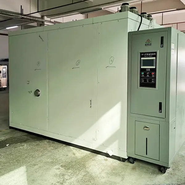
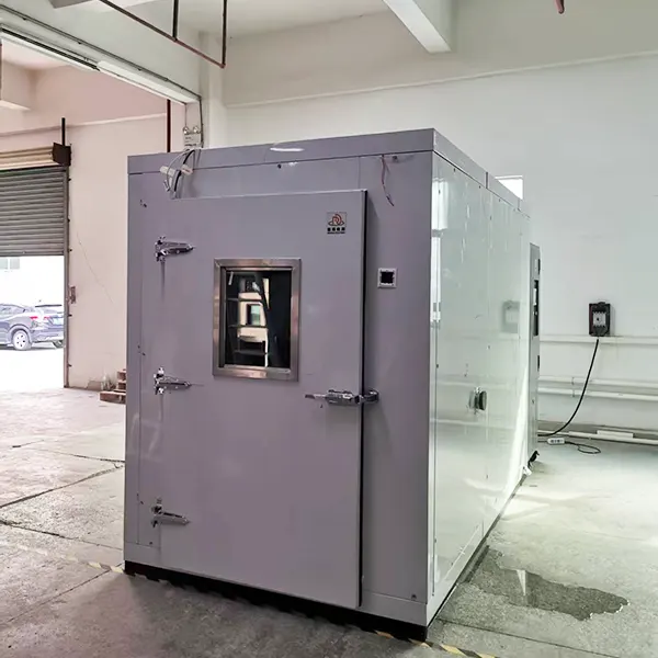
Move larger assemblies and batch fixtures into a dedicated temperature-humidity environment. The DERUI 8m³ walk-in test chamber combines a modular room structure, forced air circulation and programmable climate control for industrial product evaluation.
Choose the setup around your required environmental exposure and loading layout. For steady damp heat or humidity cycling, the useful specification is the complete temperature–RH profile, usable sample space and evidence required to assess the result.
Will the Assembly, Trolley and Test Connections Fit?
Use the walk-in format for components, assemblies or multiple specimens that require room-sized loading access. Potential applications include moisture-sensitive electronic housings, connector assemblies and industrial equipment, with endpoints selected from the applicable product test plan.
Review more than the product dimensions. Include the trolley, rack, clamps, cables and any external connections in the loading drawing. Reserve space around supply and return-air paths so a densely packed batch does not change the exposure unintentionally.
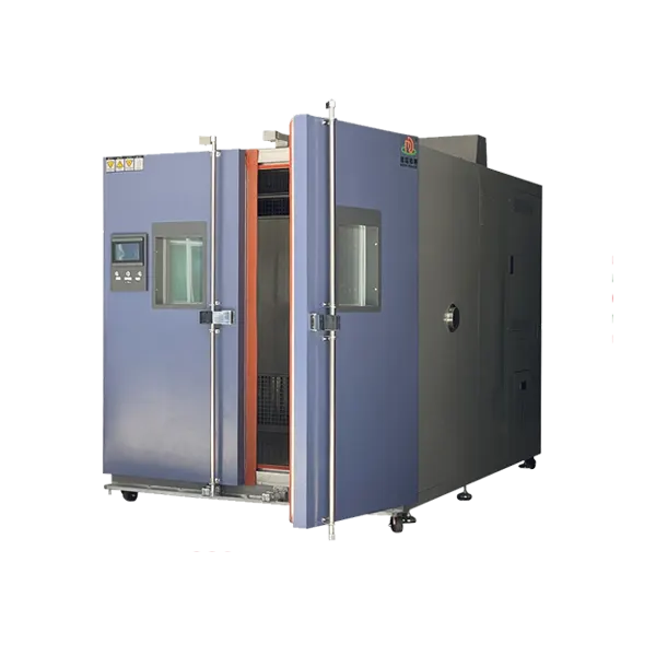
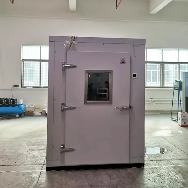
The listed room construction includes modular panels, a non-slip floor and trolley-entry arrangement. Define clear door opening, threshold or ramp, wheel loads and turning space together; an 8m³ volume does not establish a floor load rating or guarantee that a tall assembly can pass through the door.
For comparisons between design revisions, keep specimen orientation, spacing, operating state and inspection timing consistent. This makes a change in sealing, coating or electrical performance easier to distinguish from a change in how the sample was exposed.
Steady Damp Heat and Cyclic Damp Heat Are Different Test Duties
| Test objective | Exposure to define | Chamber selection question |
|---|---|---|
| Steady damp heat | Constant temperature and high humidity over a defined period, with the required condensation control | Can the selected configuration maintain the paired temperature–RH point with your load? |
| Cyclic damp heat | A prescribed sequence of temperature and humidity conditions | Can the chamber follow the complete cycle and its required moisture/condensation behavior? |
| Combined climate evaluation | Your product-specific temperature–humidity recipe and functional checks | Do transitions, specimen operation and evaluation criteria match the intended validation? |
IEC 60068-2-78 addresses steady damp heat at constant temperature without condensation on the specimen. IEC 60068-2-30 addresses cyclic damp heat. Identify the adopted standard edition, severity and full procedure before selecting the chamber configuration; these references do not represent blanket equipment certification.
Relative humidity depends on temperature. Request a temperature–RH operating envelope rather than combining the lowest temperature and highest humidity from separate range limits. Include ramp stages and humidity recovery if they are part of the test.
Condensation must match the test objective. A cold specimen entering warm humid air can collect surface moisture. Preconditioning and transition handling matter, especially when the method calls for non-condensing exposure. A high-RH display alone does not demonstrate the correct specimen condition.
Define the result you will inspect: for example, insulation performance, connector resistance, surface changes or functional operation. Environmental exposure and product acceptance are separate parts of the test, so agree the evaluation and recovery sequence before the first run.
8m³ Configuration and Published Performance References
Select one temperature-humidity configuration for the required duty. The range choices below are alternatives from the equipment series, not a promise that one installed chamber covers every listed combination. Performance references require agreed measurement and loading conditions.
| Item | Selection / published reference | Selection condition |
|---|---|---|
| Nominal volume | 8m³ | Specify internal geometry, usable working zone and loading arrangement separately. |
| Upper-temperature selections | +80 / +100 / +120 / +150 / +200°C | Series configuration alternatives; the proposal identifies the installed upper limit. |
| Lower-temperature selections | 0 / −20 / −40 / −50 / −60 / −70°C | Choose the low-temperature configuration for the required profile and thermal load. |
| Humidity selections | 30–98 / 25–95 / 20–98 / 10–98% RH | Alternative configurations, subject to the simultaneous temperature–RH envelope. |
| Published temperature deviation | ≤ ±1°C | Define setpoints, measurement locations and load conditions; do not substitute this for spatial uniformity. |
| Published temperature fluctuation | ≤ ±0.5°C | Agree the stabilization and measurement interval. |
| Published humidity error | +2 / −3% RH | Specify the operating points and verification method. |
| Published average heating / cooling | Heating 1–3°C/min; cooling 1°C/min | Reference average rates, not linear or specimen-response guarantees. Define the interval and load. |
| Cooling arrangement | Water-cooled | Match cooling-water temperature, flow, pressure and quality to the selected system. |
| Room and circulation | Modular panels; SUS304 construction; forced circulation with BTHC/PID control | Review the floor, air paths, door and specimen layout as one configuration. |
| Program capacity | Published reference: 120 programs / 1,200 segments | Confirm the supplied controller and recipe needs. |
| Record acquisition | Temperature-humidity recorder: optional | Specify channels, timestamps, sampling interval and record format if required. |
| Computer connection | Remote operation through optional computer connection | Define the supplied interface and permitted monitoring/control functions. |
| Electrical arrangement | Three-phase, four-wire | Voltage, frequency, rated demand and protection are specified for the destination installation. |
Choose the Monitoring You Need—Without Paying for Assumed Features
Climate control and visibility
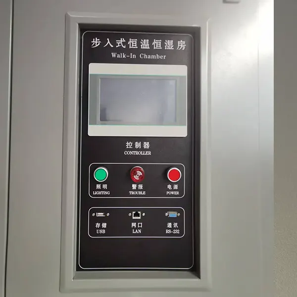
The listed programmable LCD control displays temperature and humidity. Forced circulation and balanced temperature-humidity control regulate the environment; an observation window allows visual checks without routinely opening the room.
Optional test records
Specify a recorder when traceable exposure evidence is required. Define the channels, sample interval, timestamp handling and file/report output; a live display is not the same as a retained record.
Optional computer operation
If remote operation is needed, include the computer connection and its functions in the quotation. Decide whether users need monitoring, recipe control or both, and align access with laboratory IT requirements.
For a long exposure, plan what happens when water runs low, an alarm occurs or the supply is interrupted. The published protections include a leakage circuit breaker, over-temperature alarm, phase-loss protection and water-shortage detection. Agree the response, notification and recovery policy for the actual test.
Retain sample IDs, loading photographs, the approved recipe, actual exposure records and the post-test assessment together. For powered specimens, declare heat output and define whether additional specimen sensors are required; room-air measurements cannot establish every component temperature.
Room entry must follow an approved safe-access procedure. General electrical and temperature protections do not establish battery-abuse capability or explosion containment. Identify hazardous specimens at the enquiry stage so the project can be assessed separately.
Get a Comparable Proposal and a Measurable Acceptance Plan
A useful quotation connects the intended exposure to a specific room layout and supplied equipment. Start with the product drawing and required conditions; add recording and interfaces according to your quality process. This avoids comparing prices for configurations that do not perform the same job.
| Purchase decision | Define with DERUI | Evidence to agree |
|---|---|---|
| Sample capacity | Specimen quantity, racks, trolley, spacing and point loads | Loading drawing, door clearance and approved floor arrangement. |
| Climate performance | Paired temperature–RH conditions, cycle/dwell, specimen mass and heat output | Measurements at agreed operating points and a representative application run. |
| Recording scope | Recorder or computer options, required channels and outputs | Demonstration of the supplied record workflow and sample file. |
| Site readiness | Assembly access, power, cooling water, humidity water, drains and service space | Installation drawing and utility schedule. |
| Protection and handover | Alarm actions, safe access, operating instructions and maintenance access | Functional checks and the agreed commissioning/handover scope. |
IEC 60068-3-6 provides guidance for confirming temperature-humidity chamber performance without specimens. Keep that characterization distinct from loaded application verification: racks, moisture release and powered heat can change conditions around the product.
Agree which checks occur at factory acceptance and which require the installed site, utilities or actual specimen. Record sensor locations, loading state, stabilization and acceptance limits so a completed cycle can be evaluated against a defined requirement.
Not sure which configuration you need? Send your product drawing, test method or target conditions first. Add the expected quantity, operating state and site information where available. A preliminary enquiry can establish the missing selection details without forcing you to choose an environmental range from a catalogue alone.
8m³ Walk-In Temperature Humidity Chamber FAQ
What is this 8m³ walk-in test chamber designed for?
It provides programmable temperature-humidity exposure for industrial components, assemblies and batches needing walk-in loading space. Steady or cyclic damp-heat applications require the appropriate configuration and method-specific verification.
How many specimens can fit in the room?
Capacity depends on usable dimensions, the rack or trolley, clearances, floor loads and circulation paths. Provide a loading drawing rather than calculating quantity from the nominal 8m³ volume alone.
Can it perform both steady and cyclic damp-heat tests?
Select the configuration against the complete adopted procedure. Steady and cyclic duties differ in their transitions and condensation requirements; confirm the required paired conditions and demonstrate the intended cycle.
Are a recorder and remote computer operation standard?
The current specification presents the temperature-humidity recorder and computer connection for remote operation as options. Include the functions you need in the proposal; do not assume logging, USB export or remote access from the display alone.
What utilities are required?
The published arrangement is water-cooled with a three-phase, four-wire supply. Request destination-specific electrical requirements plus cooling water, humidification water, drainage and service-clearance information.
What do I need to send for an enquiry?
Start with the specimen drawing and required test conditions or method. Add quantity, fixture/trolley dimensions, mass, powered heat output, recording needs, site utilities and any hazards so the proposed configuration addresses your actual application.
Request a Chamber Matched to Your Humidity Test
Start with Your Product Drawing and Required Conditions
Send DERUI the specimen dimensions and temperature-humidity test method or profile. Include a loading sketch if you have one. Request a proposal identifying the room arrangement, selected environmental range, recorder options, utilities and acceptance checks.
For other workspace sizes, explore the walk-in chamber range, the 10m³ walk-in temperature chamber and the 48m³ walk-in environmental chamber. Compare the loading and test duty; shared climate functions do not make these formats interchangeable.