
Custom Walk-In Temperature Humidity Chamber Built Around Your Assembly
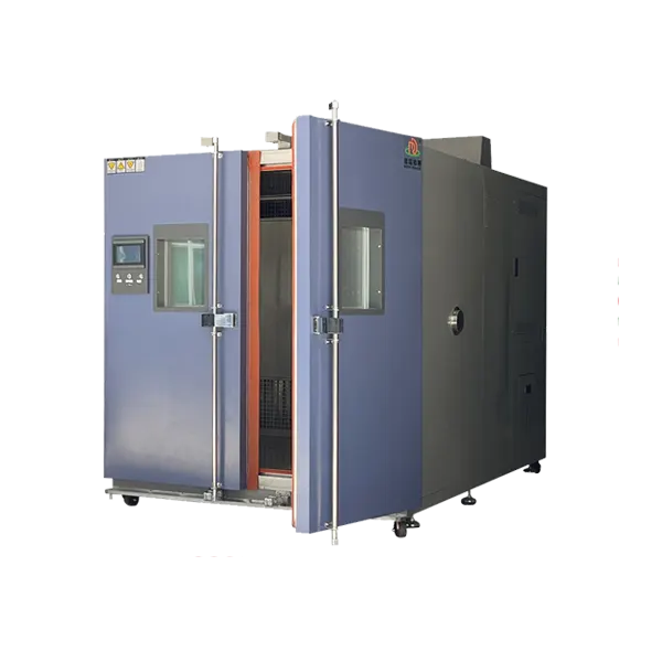
A product can fit inside a nominal chamber volume and still be difficult to load, connect or expose correctly. The DERUI 3m³ custom walk-in chamber gives you a starting format for a temperature-humidity room whose geometry, door arrangement and interfaces are developed around the actual test.
Use this modular climate-room approach when a standard cabinet layout does not suit your assembly or fixture. Begin with the product drawing, required environmental profile and available installation space to define a practical configuration.
Make the Door, Workspace and Connections Fit the Test
This page presents the 3m³ reference product, not an unlimited-capacity room. Customization starts with the complete specimen envelope: product, fixture, supports, cables and any movement needed for loading or inspection.
For a tall assembly, prioritize door height and internal clearance. For a wide fixture, check the clear opening and turning route. For rack-mounted samples, reserve supply and return-air space rather than filling the room to its walls. Internal volume alone does not settle these questions.
The listed construction uses modular blocks and permits project-specific room and door dimensions. Single or double doors and left/right opening arrangements are described in the configuration. Select the arrangement with the loading route and laboratory layout, including space to open the door fully.
Potential applications include low/high-temperature exposure, programmed temperature changes and damp-heat testing of complete machines or larger components. Select the configuration against the adopted procedure and actual load; customization does not automatically add other exposure types.
Customize the Details That Affect Daily Testing
| Design decision | What to provide | What to define in the proposal |
|---|---|---|
| Internal geometry | Specimen/fixture dimensions and loading quantity | Usable working zone, circulation clearances and overall internal dimensions. |
| Door and handling route | Trolley or fixture envelope, turning space and entry direction | Clear opening, hinge side, threshold/ramp requirements and access route. |
| Rack and floor | Sample mass, rack supports and wheel/point loads | Floor and rack capacities for the actual contact loads; volume is not a load rating. |
| Test interfaces | Cable bundles, sensors, fluid lines and operating state | Port locations, usable sizes, sealing and routing outside the room. |
| Environmental duty | Temperature–RH recipe, transitions, dwell and internal heat output | Selected operating envelope, heating/cooling duty and application acceptance cycle. |
| Operator workflow | Access permissions, alarms and record requirements | Supplied controls, notification functions and required output or data interfaces. |
The published test-hole reference is 50mm. A cable bundle, plug or fluid connection may need a different usable opening or additional ports. Review the full connection route: passing a lead through an unsealed door can change the exposure and damage the seal.
Door access control, environmental protection and test records solve different problems. A fingerprint lock may control access, but it does not replace a safe release procedure. An alarm message may notify an operator, but it does not establish that a test was completed correctly. Specify each function for the intended workflow.
3m³ Reference Configuration and Performance Schedule
The published reference configuration below supports an initial project discussion. Final dimensions, environmental performance and interfaces are established around the selected test load and installation conditions.
| Item | Published reference / configuration basis | Specification condition |
|---|---|---|
| Reference volume | 3m³ | Final internal dimensions and usable zone follow the approved project layout. |
| Published temperature reference | −60°C to +150°C | Define the ordered range with specimen mass, powered heat output, site conditions and test profile. |
| Humidity configuration | Specify paired temperature–RH operating points | Request the selected humidity range and operating envelope with the proposal. |
| Published spatial uniformity | Temperature ±2°C; humidity ±3% RH | Specify measurement points, setpoints, stabilization and load conditions. |
| Published temperature fluctuation | ±0.5°C | Define the measurement location and observation period; do not confuse fluctuation with spatial uniformity. |
| Published heating-time reference | −40°C to +150°C: ≤45 minutes | Reference interval only. Loading and measurement conditions must be agreed; not a specimen or linear-ramp guarantee. |
| Published cooling-time reference | +20°C to −60°C: ≤100 minutes | Reference interval only. Verify the agreed load and environmental-system configuration. |
| Control | Published 10-inch color LCD programmable system | Define recipe operation, required records and supplied interfaces. |
| Cooling method | Air-cooled | Provide installation ambient conditions, ventilation and service space; obtain heat-rejection requirements. |
| Published supply reference | AC 380V ±10%, 50Hz, three-phase with neutral and protective earth | Confirm destination supply, rated power/current and wiring against the electrical specification. |
| Door and sample rack | Project-specific arrangement | Clear door opening, rack dimensions and capacities belong in the mechanical drawing. |
| Test-hole reference | 50mm diameter | Specify additional or different openings where the test interfaces require them. |
| Access, notification and printing | Fingerprint access, SMS alarm and micro-printer are described configuration functions | Identify the supplied functions and their implementation in the ordered scope; do not infer logging or export capabilities. |
| Installation environment | Specified for the selected project | Agree ambient temperature/humidity, ventilation, utilities and maintenance clearances before ordering. |
Account for the Load—and the Heat Released into the Laboratory
Passive or powered specimens
A heavy passive specimen takes time to stabilize. A powered assembly adds internal heat that affects cooling and local air temperatures. Declare mass, material, operating heat output and duty cycle with the test profile.
Air-cooled installation
Plan where rejected heat goes and how cooling air reaches the system. An enclosed service corner or recirculated hot exhaust can undermine the intended duty. Keep intake/exhaust paths and maintenance space in the layout.
Temperature–humidity transitions
Specify temperature and RH together, including the transition sequence. Decide whether condensation is required or prohibited and how the specimen is conditioned before exposure and evaluated afterward.
The room’s control-sensor reading is not a measurement of every component in an assembly. Where the method depends on specimen stabilization, use the required specimen sensors and dwell-start rule. For batches, define the loading arrangement and the measurement locations used to establish exposure consistency.
Uniformity and fluctuation describe different behavior: spatial differences across the working zone versus variation over time at a location. Use the correct definition when setting acceptance limits rather than treating every “±” number as the same performance claim.
The published protections include leakage-current and over-temperature safeguards. Agree the fault response, specimen-power handling and safe-access procedure for the ordered system. Battery hazards, combustible materials or pressure systems need a separate project risk review; a climate room is not automatically an abuse-testing enclosure.
Define the Drawing, Acceptance Cycle and Delivery Scope Together
A useful custom proposal is more than a room size and a price. It connects the approved loading drawing to the environmental duty, site installation and measurable acceptance criteria. Agree these details before manufacturing changes become expensive.
| Project stage | Decision to complete | Record to agree |
|---|---|---|
| Layout review | Internal geometry, clear door opening, floor/rack loads and interface positions | Approved mechanical and loading drawing. |
| Performance specification | Required paired conditions, transition intervals, dwell, load and tolerances | An environmental schedule with explicit test and measurement conditions. |
| Controls and services | Supplied access/alarm/record functions, electrical demand and heat rejection | Configuration list, electrical information and site-preparation requirements. |
| Factory acceptance | Dimensions, controls, protections and agreed environmental checks | Factory results with sensors, load state, recipe and acceptance limits identified. |
| Site commissioning | Installed utilities, representative application cycle and operator handover | Site acceptance scope, operating instructions and handover records. |
IEC 60068-3-6 describes performance confirmation of temperature-humidity chambers without specimens. Keep empty-room characterization separate from loaded application checks; an obstructed airflow path or powered specimen can change the environment near the product.
Agree the manufacturing and delivery schedule after the configuration is defined. Include site readiness, assembly access and commissioning responsibilities rather than assuming that a generic lead time covers every custom project.
For the first enquiry, a product drawing, required test conditions and site sketch are enough to start the discussion. Add fixture mass, powered heat output and interface needs where available. Request a proposal that lists both the supplied equipment and the checks needed to accept it.
3m³ Custom Walk-In Chamber FAQ
Is this page for a 3m³ product or the complete walk-in range?
This page presents a 3m³ reference custom temperature-humidity chamber. Room geometry and configuration are developed for the project; other workspace sizes should be selected separately from the walk-in range.
What can be customized?
Define internal dimensions, usable workspace, door opening and direction, racks, floor capacity, interface positions and the environmental duty. The proposal identifies the functions and dimensions supplied for your project.
What temperature and humidity range should I request?
The published temperature reference is −60°C to +150°C. Provide the paired temperature–RH points and test load so the selected humidity envelope and actual performance requirements can be specified in the proposal.
Are the heating and cooling times guaranteed for my specimen?
The published interval references are −40°C to +150°C within 45 minutes and +20°C to −60°C within 100 minutes. They do not establish specimen response or linear ramps. Agree measurement and load conditions, then verify the required cycle.
Does air cooling remove the need for site preparation?
No. The laboratory must accommodate heat rejection, intake/exhaust airflow, electrical supply, humidity-water/drain arrangements where required, loading access and service space. Obtain the installation requirements for the selected system.
What information should I send for a custom quotation?
Start with product and fixture drawings, required temperature-humidity conditions and the available site layout. Add mass, point loads, operating heat output, interfaces, records and protection needs; agree acceptance and schedule with the final configuration.
Request a Layout and Configuration for Your Product
Send Your Product Drawing, Test Conditions and Site Sketch
Tell DERUI what must fit inside, how it will be loaded and which environmental conditions it must experience. Request a custom proposal covering the room geometry, door, interfaces, air-cooled system and acceptance scope.
Need a different room size? Explore the walk-in chamber range. Review the 8m³ temperature-humidity chamber, 10m³ temperature chamber or 48m³ environmental chamber against your loading and test requirements.