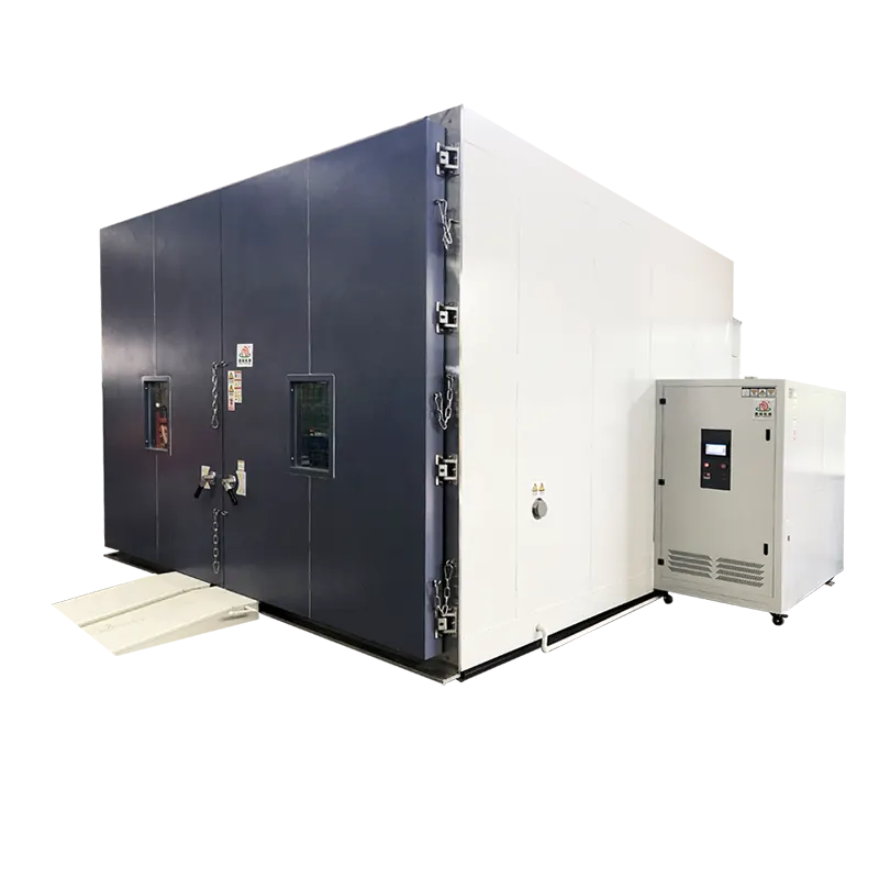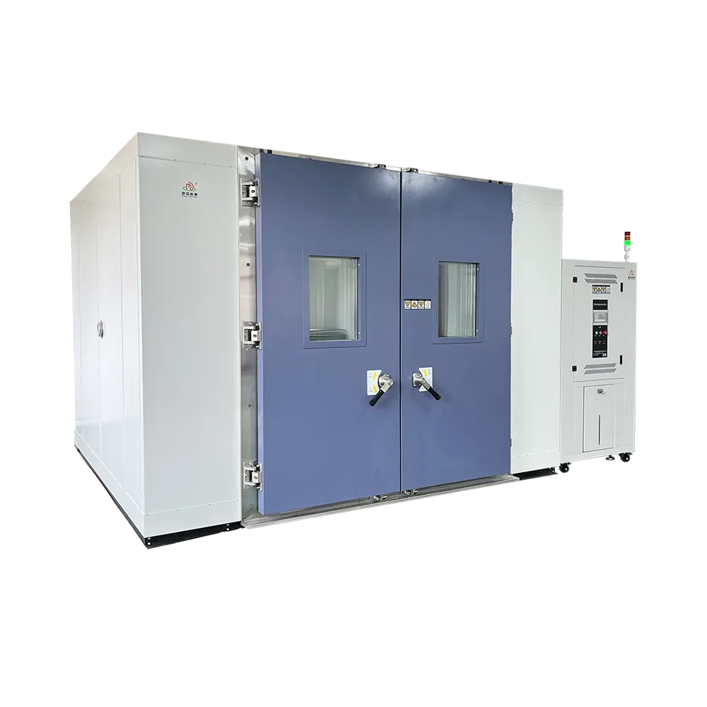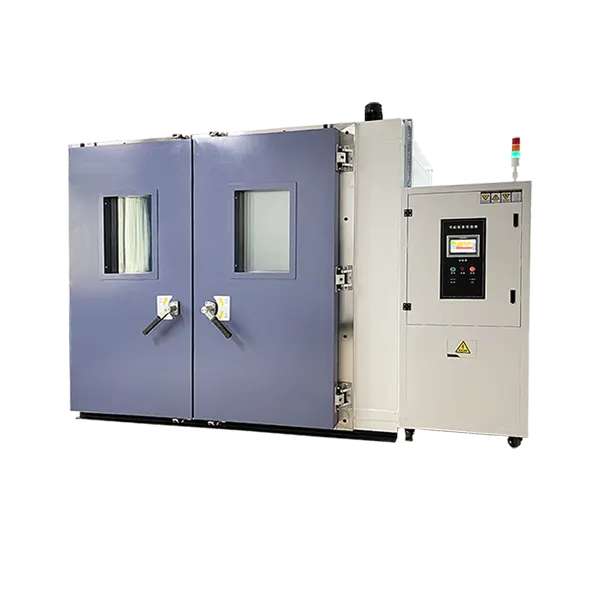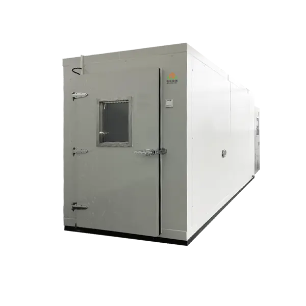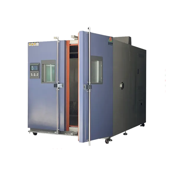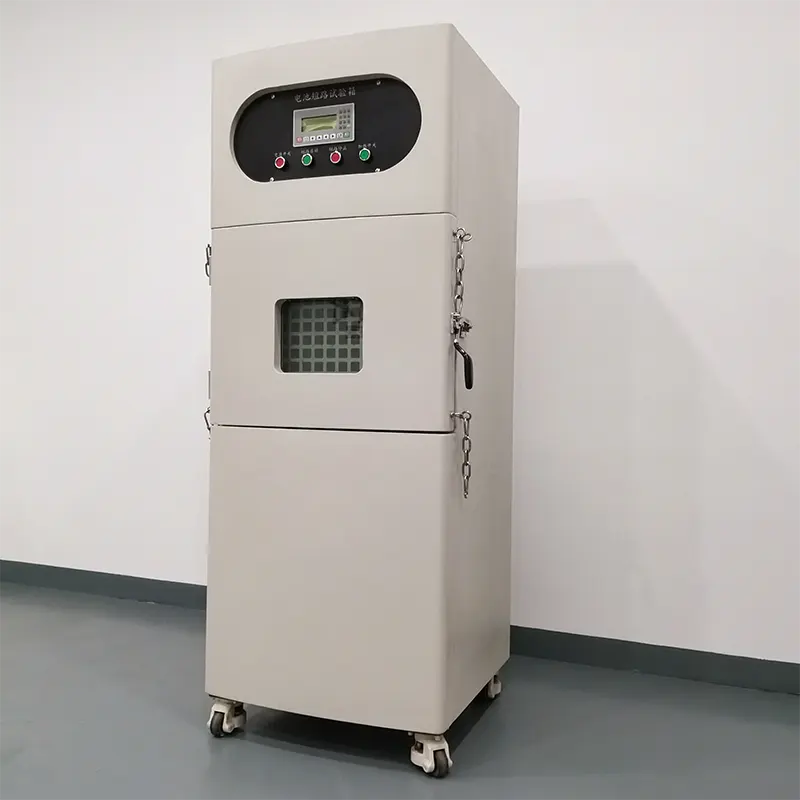
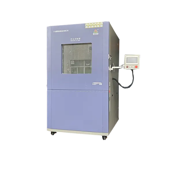

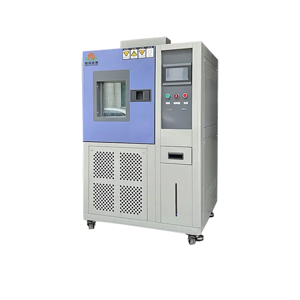
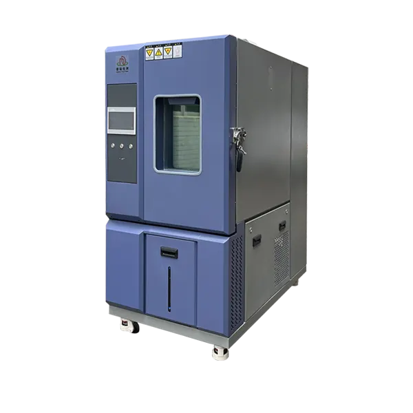
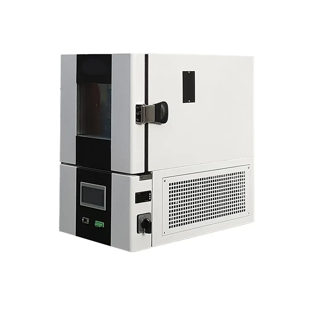
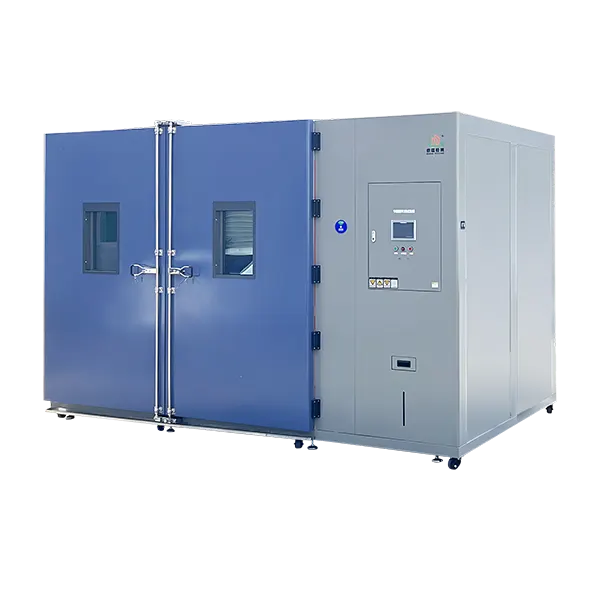
10m³ Walk-In Temperature Chamber for Programmed Heating, Cooling and Dwell Tests
Test large components, assemblies and rack-mounted specimens through controlled temperature profiles in a walk-in workspace. The DERUI 10m³ chamber combines programmable temperature and humidity operation with a water-cooled environmental system and controller-based test records.
Specify the required heating and cooling sequence around the real load. The selected temperature limits, transition interval, specimen mass and operating heat output determine whether a configuration can reproduce your test—not the nominal volume alone.
Fit the Assembly—and Reproduce Its Temperature Profile
The 10m³ format is intended for industrial components, semi-finished goods and completed products that need a larger loading space than a cabinet provides. Review the assembly, supporting fixture and cable routes together before selecting the working dimensions.
For electronics and electromechanical assemblies, define the functional checks required at hot and cold conditions. For batch specimens, define spacing and monitoring positions so one sample or rack does not unintentionally shield another from the circulating air.
A typical profile contains a starting condition, a controlled transition, a dwell, a return transition and a repeat count. The chamber recipe should reproduce this sequence while preserving a record of actual conditions and any interruption.
This is a temperature-humidity chamber, not a temperature-only room. Include humidity stages when your method requires them, with the simultaneous temperature–RH operating points identified in the selected configuration.
10m³ Technical Parameters and Configuration Choices
Select the temperature and humidity configuration for your actual test. The range selections below describe alternatives; the ordered chamber must have one defined configuration and a measurable performance specification.
| Parameter | Selection / published reference | Application condition |
|---|---|---|
| Nominal workspace | 10m³ | Internal dimensions, usable zone, door opening and floor capacity are specified with the loading drawing. |
| High-temperature limit selections | +80 / +100 / +120 / +150 / +200°C | Alternative configurations, not simultaneous ratings for one installed machine. Select the required upper limit in the proposal. |
| Low-temperature limit selections | 0 / −20 / −40 / −50 / −60 / −70°C | Alternative configurations. Confirm the chosen low/high combination with the required load and installation conditions. |
| Humidity range selections | 30–98 / 25–95 / 20–98 / 10–98% RH | Select the installed humidity configuration and its temperature–RH envelope. These are not interchangeable universal ratings. |
| Published temperature deviation | ≤ ±1°C | Agree the measurement definition, setpoints, sensor positions and load conditions. This value is not a substitute for a separate uniformity requirement. |
| Published temperature fluctuation | ≤ ±0.5°C | Define the stabilization and observation period used for verification. |
| Published humidity error | +2 / −3% RH | Confirm applicable temperature–RH points and measurement conditions. |
| Published average heating rate | 1–3°C/min | Average-rate reference; interval and loading conditions must be specified. Not a guaranteed linear or specimen rate. |
| Published average cooling rate | 1°C/min | Average-rate reference; verify the selected interval, load and powered heat output. |
| Cooling arrangement | Water-cooled | Obtain required water temperature, flow, pressure, quality and heat-rejection duty for the selected system. |
| Control and program capacity | PID program control; 120 programs / 1,200 segments | Allocate stages and cycles around the test recipe; confirm the controller implementation in the ordered configuration. |
| Construction material | SUS304 stainless steel | Specify the required surface, floor construction and load capacity in the mechanical configuration. |
| Electrical arrangement | Three-phase, four-wire | Destination voltage, frequency, rated power and protective-device requirements are project-specific. |
| Operating functions | Programmed temperature and humidity | Controller functions and interfaces are detailed below; agree the supplied configuration before purchase. |
Average Air Rate Is Not a Guaranteed Specimen Rate
For a programmed temperature cycle, define what is being controlled and measured. Chamber air can reach the target before a heavy component stabilizes. A temperature displayed at the control sensor does not establish that every sample has completed its required exposure.
| Requirement | Define in the test plan | Why it matters |
|---|---|---|
| Ramp or transition | Start/end temperatures, average or linear rate, and air or specimen measurement | An average rate over one interval does not establish the slope across every part of a cycle. |
| Dwell | Start condition, tolerance and duration | Starting the dwell too early can shorten the specimen’s intended exposure. |
| Loading | Specimen and fixture mass, layout, material and internal heat output | Thermal mass affects response; powered heat affects cooling duty and local temperatures. |
| Humidity stages | Paired temperature–RH points and condensation requirements | Separate range limits do not establish every simultaneous operating condition. |
| Functional monitoring | Operating state, cable interfaces, measurement points and termination rules | A repeatable exposure needs repeatable specimen operation and result assessment. |
When discussing temperature-change testing under IEC 60068-2-14, identify the adopted edition and exact procedure. Match its transition, exposure and specimen requirements to a demonstrated chamber capability. A standard name in a quotation does not establish suitability for every test severity.
Thermal cycling is not rapid-transfer thermal shock. This page describes programmed heating and cooling in a walk-in room. Do not substitute it for a hot-to-cold transfer system, or assume fast-rate ESS performance from the published average rates.
Before acceptance, run the specified cycle with a representative load or an agreed substitute. Record chamber air and any required specimen temperatures, then evaluate the rate and dwell using the same definitions as the purchase specification.
Build a Traceable Recipe, Not Just a Completed Cycle
Recipe and access control
The published controller functions include Chinese/English touchscreen menus, password-based access, scheduled operation and program status displays. Set permissions so routine operation does not change an approved recipe unnoticed.
Curve recording and export
The published functions include paperless curves, timestamped records, XLS table export and USB data export. Specify which channels, sampling interval, file format and identifiers must appear in your test record.
Network and interruption handling
Ethernet/TCP/IP monitoring and selectable power-failure recovery are described in the listing. Align network access with your IT rules; choose restart, resume or stop behavior appropriate to the test, rather than resuming every cycle automatically.
Retain the specimen ID, approved recipe, actual temperature-humidity records, operating state, alarm history and post-test assessment together. A chamber record shows environmental exposure; functional inspection or product acceptance remains a separate evaluation.
If you need specimen thermocouples or other independent acquisition channels, define them separately from the controller’s air-temperature record. Test the actual export process during handover, including timestamps and how an operator associates a file with the correct specimen.
The listed protections include compressor pressure/current/temperature protection, fan overheating protection, temperature limits and electrical protection. Define alarm thresholds, specimen power isolation and the required response to a fault in the ordered system. Battery or hazardous-material testing requires an additional risk review; these protections are not evidence of explosion containment.
Prepare the Water Circuit, Loading Layout and Acceptance Cycle
A water-cooled installation needs more than a suitable electrical connection. Establish the water supply and heat-rejection arrangement before delivery. Request an installation drawing identifying service connections, environmental-system access and the loading space around the chamber.
| Project decision | Information to provide / request | Acceptance check |
|---|---|---|
| Cooling-water services | Available inlet temperature, flow, pressure, water quality and return arrangement | Verify the selected system’s required services and record conditions during the acceptance run. |
| Mechanical loading | Product, rack and trolley dimensions; distributed and point loads | Review clear access, floor capacity and supply/return-air clearance. |
| Electrical and interfaces | Site voltage/frequency, operating specimen power, signal and fluid connections | Verify supply compatibility, protective functions and the ordered test-port arrangement. |
| Environmental performance | Selected range, rate interval, tolerances, paired RH points and representative load | Measure performance against the agreed recipe and measurement definitions. |
| Controls and handover | Recipes, export needs, alarm responses and maintenance access | Demonstrate control functions, data export and safe recovery from the agreed fault scenarios. |
Separate factory acceptance testing from checks dependent on the installed site and actual specimen. IEC 60068-3-7 provides guidance for loaded temperature-chamber measurements in cold and dry-heat testing. Use applicable guidance in the acceptance plan without turning it into a claim of product certification.
Compare proposals using the same selected range, test load, heat output, rate definition, water conditions and acceptance scope. If energy use is important, request measured consumption under a defined duty; compare equivalent cycles instead of relying on an unsupported percentage saving.
10m³ Walk-In Temperature Chamber FAQ
Is this a temperature-only chamber?
No. The 10m³ listing specifies programmed temperature and humidity operation. Select the humidity configuration and paired operating points required by your test.
Is every listed temperature range available in one chamber?
No. Upper and lower limits in the parameter schedule are configuration selections. The proposal must identify the installed temperature range and performance conditions for your load.
Are the heating and cooling rates linear or measured on the specimen?
The published values are average heating of 1–3°C/min and average cooling of 1°C/min. They do not establish a linear ramp or specimen response. Define the interval, measurement location and load, then verify the required cycle.
Can test records be exported?
The published controller functions include curve recording, timestamped records and XLS/USB export. Specify required channels and record formats, and demonstrate the supplied export function during acceptance.
What site services does the chamber require?
The published arrangement is water-cooled with a three-phase, four-wire electrical supply. Obtain the selected voltage, frequency, power and cooling-water requirements together with the installation drawing.
What should I send for a configuration proposal?
Send specimen and fixture drawings, mass and operating heat output, temperature-humidity recipe, rate and dwell definitions, sample quantity, interfaces, site utilities and acceptance requirements. Include any sample-specific hazards.
Request a 10m³ Temperature-Cycling Configuration
Send Your Cycle, Test Load and Site Utilities
Provide your low/high conditions, heating and cooling requirements, dwell definition, humidity stages, load drawing and internal heat output. Request a proposal that identifies the selected configuration, cooling-water duty, records and acceptance cycle.
Compare room formats in the walk-in test chamber range. Review the 8m³ walk-in test chamber for a smaller loading envelope, or the 48m³ walk-in environmental chamber for a substantially larger project. Choose from the actual profile and loading requirements, not volume alone.