


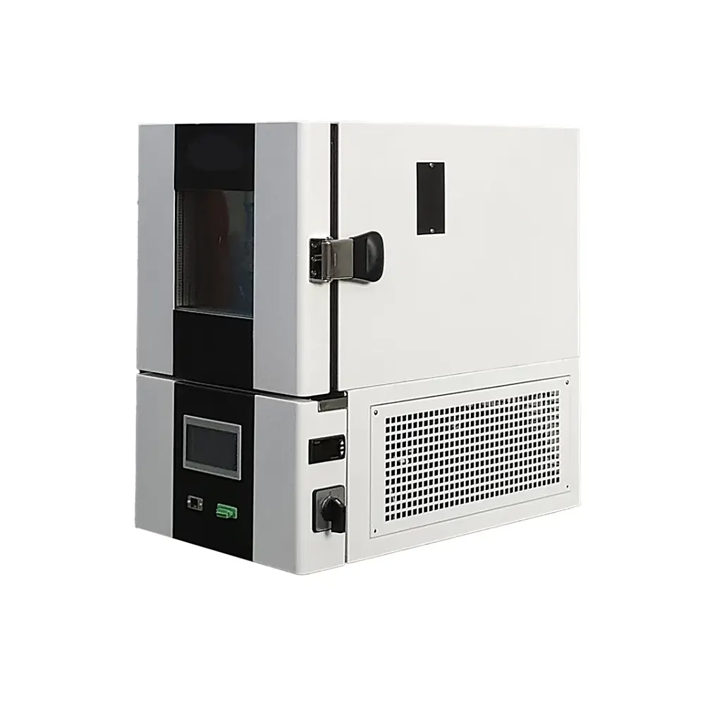
Vibration, Temperature and Humidity in One Coordinated Test System
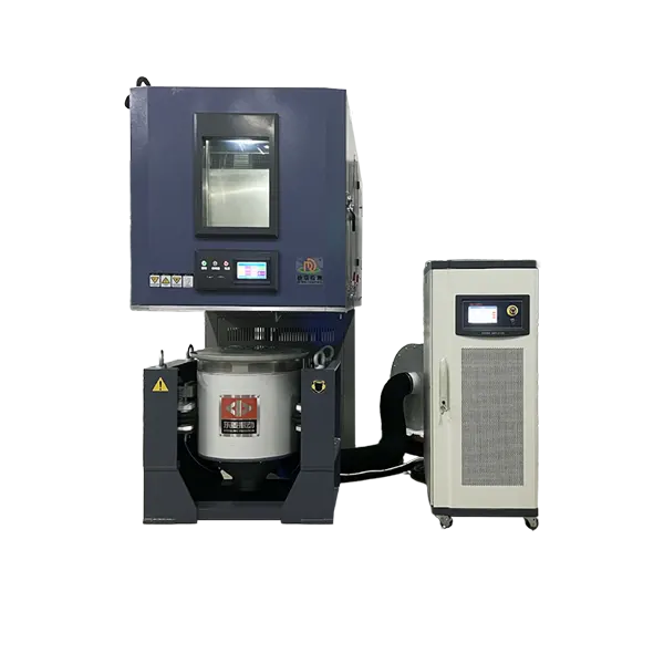
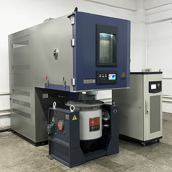
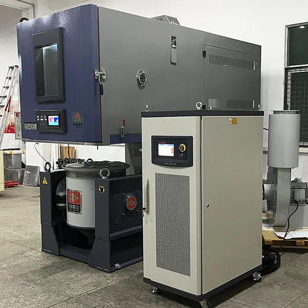
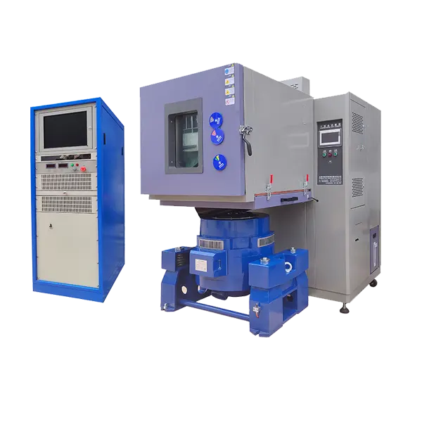
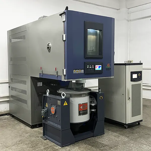
The DERUI vibration climatic test chamber integrates a climatic enclosure with a compatible electrodynamic shaker or slip table, allowing specimens to be exposed to programmed vibration and temperature—and, where the selected operating envelope permits, humidity—during the same test sequence.
The system is configured around the specimen mass, fixture, vibration profile, chamber interface, thermal load and applicable test method. DERUI reviews both the chamber and shaker requirements before confirming performance, because the achievable acceleration, frequency, temperature change and humidity conditions depend on the complete installed system.
Why Combined Environmental Testing Matters
Separate climate and vibration tests are useful, but they may not reproduce interactions that appear when mechanical and thermal stresses overlap. Temperature can change material stiffness, connector contact resistance and seal behavior; vibration can then expose marginal solder joints, fasteners, harnesses or interfaces under those conditions.
Find interaction failures
Investigate intermittent electrical contact, solder fatigue, connector fretting, fastener loosening, seal movement and structural resonance while the specimen is at a defined climatic condition.
Reproduce an approved profile
Coordinate shaker control, chamber setpoints, specimen operation and monitoring from a documented test plan rather than applying arbitrary maximum stresses.
Improve test evidence
Record acceleration control data alongside chamber temperature, humidity and specimen functional measurements to support engineering review and failure analysis.
Reduce handling between systems
A combined installation can reduce specimen remounting and help preserve fixture, wiring and monitoring arrangements across multi-stage test sequences.
How the Chamber and Shaker Work Together
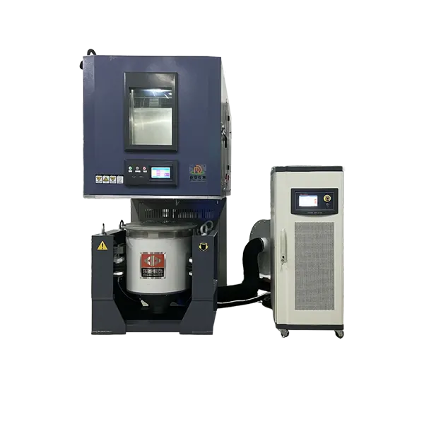
Climatic enclosure
The insulated chamber provides programmed temperature conditions and an application-dependent humidity envelope. Flexible thermal barriers around the interface limit air leakage while allowing shaker motion.
Electrodynamic shaker
The shaker, power amplifier, cooling system and vibration controller generate the specified sine, random or shock input within the force, displacement, velocity and acceleration limits of the selected system.
Vertical and horizontal axes
A vertical armature interface supports vertical testing. A horizontal slip table can be integrated when lateral axes are required. Chamber geometry and movable sections must match the selected orientation.
Measurement and protection
Control and response accelerometers, chamber sensors and specimen channels provide feedback. Abort limits should protect the specimen, fixture, shaker and chamber interface if the response leaves the approved envelope.
System Parameters Confirmed Before Quotation
| Configuration area | Information required | Why it controls the design |
|---|---|---|
| Specimen and fixture | Dimensions, mass, center of gravity, mounting pattern and fixture mass | Determines chamber space, shaker force, overturning moment and interface design |
| Vibration profile | Frequency range, PSD or sine level, shock pulse, duration and excitation axes | Determines shaker, amplifier, armature, slip table and controller capability |
| Climate profile | Temperature limits, change rate, dwell time, humidity points and simultaneous-operation requirement | Determines refrigeration, heating, humidification and interface sealing capacity |
| Specimen heat load | Powered state, heat dissipation, duty cycle and cooling connections | Powered specimens may materially reduce temperature performance |
| Instrumentation | Control strategy, accelerometer channels, thermocouples, electrical monitoring and data export | Determines measurement hardware, feedthroughs and synchronized reporting |
| Installation site | Floor, doorway, power, cooling water or air, drainage, noise and destination requirements | Determines utilities, isolation and safe installation arrangements |
Final temperature, humidity, frequency, force, displacement, velocity, acceleration, payload and change-rate values must come from the approved technical quotation. They should not be inferred from generic ranges published for another shaker or chamber configuration.
Standards and Test-Plan Alignment
| Reference | Primary purpose | How to use it during configuration |
|---|---|---|
| IEC 60068-2-64 | Broadband random vibration testing | Confirm test spectrum, control method, axes, duration and specimen mounting from the relevant specification |
| IEC 60068-2-6 | Sinusoidal vibration testing | Confirm frequency range, amplitude or acceleration, sweep rate and endurance conditions |
| IEC 60068-2-27 | Shock testing | Confirm pulse shape, severity, direction and number of shocks within the selected shaker capability |
| MIL-STD-810 Method 514 | Tailored vibration environments for materiel | Use the required revision, category, procedure and mission profile; do not substitute a generic spectrum |
| ISO 16750-3:2023 | Mechanical loads for road-vehicle electrical and electronic equipment | Select conditions for the relevant mounting location and product program |
| ISO 16750-4:2023 | Climatic loads for road-vehicle electrical and electronic equipment | Coordinate the climatic test requirement with the mechanical-load plan only where the product specification calls for it |
For automotive planning, see DERUI’s ISO 16750 automotive electronics testing guide. For aerospace equipment, review the DO-160 and MIL-STD-810 environmental test overview.
Recommended Combined-Test Workflow
- Define the requirementRecord the standard edition, product specification, vibration profile, climate sequence, operating state, axes and acceptance criteria.
- Assess specimen and fixtureCalculate moving mass, review center of gravity and mounting stiffness, and check that fixture resonances will not invalidate control.
- Configure instrumentationIdentify control and response accelerometers, chamber sensors, specimen power, signal monitoring and abort channels.
- Run low-level checksPerform fixture and specimen resonance checks at an appropriate low input before applying the qualification severity.
- Verify climatic stabilizationConfirm specimen temperature and permitted humidity conditions before or during vibration as required by the plan.
- Execute and monitorRecord control, response, chamber and functional data; document any interruption, limiting or out-of-tolerance condition.
- Inspect and reportComplete visual, electrical, mechanical and functional checks using the defined pass/fail criteria.
How to Select the Correct Combined System
Size the shaker from the full moving mass
Include specimen, fixture, armature or head expander and any moving interface. Force alone is insufficient: displacement, velocity, frequency, payload and overturning moment can each become the limiting factor.
Define the usable climatic envelope
Ask for performance at the required specimen heat load and interface arrangement. Extreme temperature, high humidity and rapid change are not necessarily available simultaneously.
Choose the required axes
Confirm whether the test needs vertical excitation, horizontal excitation through a slip table, or specimen reorientation. This affects chamber movement, seals, floor space and installation.
Plan cables and services
Power, data, cooling, pneumatic and fluid connections must tolerate vibration and temperature while preserving chamber sealing and fixture freedom.
Define control and abort logic
Specify averaging, notching or force limiting only where the test plan permits it. Establish acceleration, displacement, temperature and specimen-response abort limits before the run.
Review laboratory integration
Check foundation, isolation, acoustic treatment, cooling utilities, electrical power, doorway access and service clearance before approving the layout.
Typical Applications
Automotive and EV electronics
Controllers, sensors, lighting, power electronics, connectors and battery-related components evaluated for location-specific mechanical and climatic loads.
Aerospace and defense
Avionics, electronic assemblies, payload equipment and vehicle hardware tested to an approved mission or installation profile.
Electronics and semiconductors
Assemblies, solder joints, connectors and housings monitored for intermittent or fatigue-related failures under controlled combined stress.
Telecom and industrial equipment
Outdoor electronics, control equipment and network hardware evaluated under their specified operational or transport environment.
Safety, Verification and Maintenance
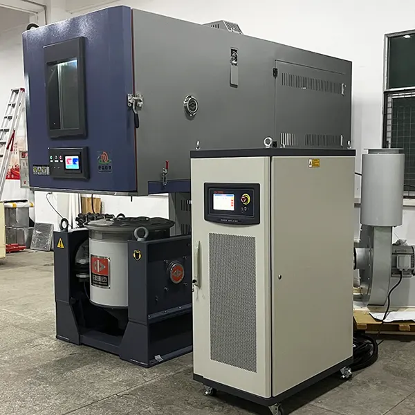
Protective functions
- Independent chamber over-temperature protection
- Shaker displacement, velocity, acceleration and amplifier protection
- Door and interface interlocks appropriate to the configuration
- Emergency stop and test abort logic
- Specimen-specific smoke, gas or electrical protection where required
Verification program
- Calibrate chamber and vibration measurement channels at documented intervals
- Verify fixture and control accelerometer installation before each program
- Survey climatic performance using the applicable laboratory procedure
- Inspect flexible seals, feedthroughs, cooling lines and fasteners
- Follow the chamber and shaker manufacturers’ maintenance schedules
DERUI provides a one-year whole-machine warranty, lifetime technical consultation, remote video guidance and operator training. Overseas installation can be arranged as a separately quoted service, and spare-parts support is available for up to ten years.
Vibration Climatic Test Chamber FAQs
Can the climate chamber and shaker operate independently?
This is normally possible in a properly designed integrated system, but the permitted modes depend on the ordered controls and mechanical interface. Confirm vibration-only, temperature-only and humidity-only operating modes in the technical quotation.
How is the required shaker force calculated?
Force estimation begins with the complete moving mass and target acceleration, but final sizing must also evaluate PSD, shock pulse, displacement, velocity, frequency, fixture dynamics, armature limits and overturning moment. A single simplified force formula is not sufficient for system selection.
Can maximum vibration, minimum temperature and maximum humidity be used simultaneously?
Not necessarily. Each system has a combined operating envelope. Humidity is especially constrained near temperature extremes, while specimen heat load and interface leakage affect chamber performance. State the simultaneous conditions in the RFQ.
Can thermal shock be combined with vibration?
A conventional single-chamber vibration climatic system provides controlled temperature change, not an automatic multi-zone thermal-shock transfer test. Specialized equipment may be engineered for a defined requirement, but it should be treated as a separate project.
What information should be included in an RFQ?
Send the standard and profile, specimen and fixture masses, dimensions, mounting drawing, vibration axes, frequency/PSD/shock requirements, climate profile, heat load, electrical monitoring, chamber ports, laboratory utilities and destination country.
How is the installed system accepted?
Define factory and site acceptance tests before ordering. Typical checks include chamber functions, climatic performance, shaker limits, control and response channels, interface sealing, safety interlocks, data export and a representative combined profile.
Request a Combined Environmental System Review
Send the specimen, fixture, vibration profile, climate sequence and laboratory utilities. DERUI will review the shaker, chamber, interface, instrumentation and installation requirements as one coordinated system.
- Vertical shaker and horizontal slip-table configurations
- Customized chamber, ports and specimen monitoring
- Destination voltage and controller-language options
- Factory testing, training and technical documentation