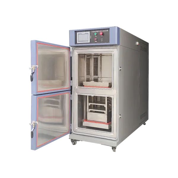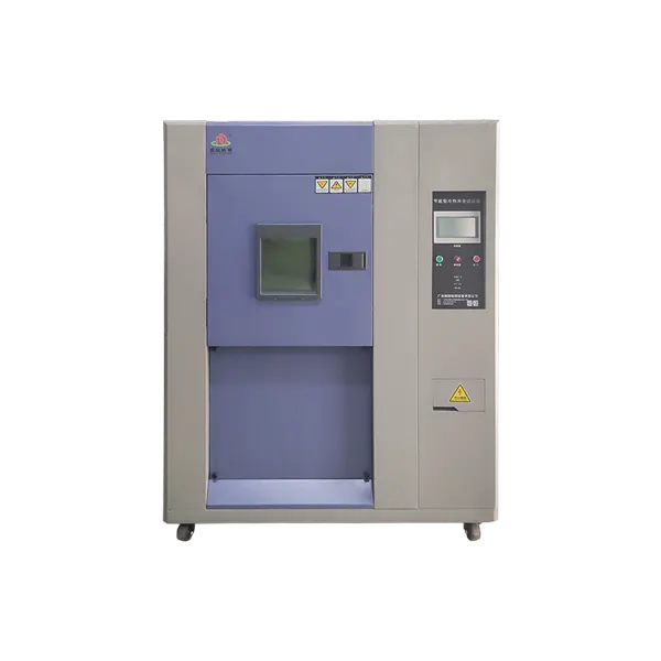
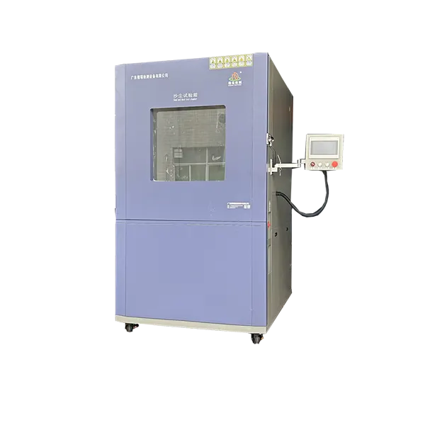

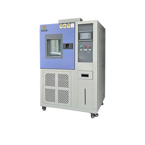
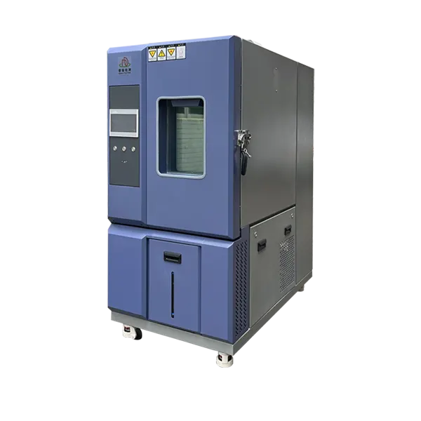
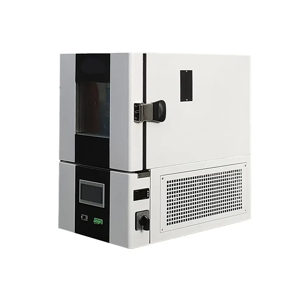
DR-H203-50 Energy-Saving Temperature Shock Test Chamber
Combine rapid hot–cold exposure with capacity matching, insulated zone management and measurable energy reporting. Select the chamber around the required transfer, loaded recovery, specimen demand and cycle profile—then compare energy consumption under the same conditions.
What Energy-Efficient Thermal Shock Must Deliver
Thermal shock can reveal failures caused by unequal expansion and contraction, including solder-joint cracking, delamination, seal leakage, coating separation and intermittent electrical faults. Lower energy use is useful only when the required exposure remains valid.
Maintain the required shock profile
Hot/cold conditions, transfer, recovery, dwell and cycle count must remain within the approved procedure.
Match capacity to the specimen
Workspace, specimen mass, fixtures and powered heat determine stored thermal capacity and recovery demand.
Reduce uncontrolled zone losses
Insulation, seals and controlled transfer openings reduce heat exchange between stored hot and cold environments.
Measure, do not assume
Compare total kWh using the same cycle, load, ambient condition, cooling method and measurement boundary.
Published DR-H203-50 Baseline
| Item | Published value | Project confirmation |
|---|---|---|
| Model | DR-H203-50 | Confirm usable workspace and specimen envelope |
| Hot-zone range | +60°C to +150°C | Confirm setpoint, dwell and tolerance |
| Cold-zone options | 0°C to -40°C or 0°C to -55°C | Select the project configuration |
| Heat-storage preparation | Room temperature to +180°C within 35 min | Zone preparation; not specimen response time |
| Cold-storage preparation | Room temperature to -55°C within 60 min | Confirm ambient and load condition |
| Conversion time | 2–10 s | Define basket transfer or airflow switching architecture |
| Recovery/stabilization | 5 min | Confirm sensor point, tolerance and representative load |
| Supply | AC380V, 50/60Hz, three-phase | Confirm site current and cooling utilities |
| Controller | 7-inch or 10-inch touchscreen | Confirm programmes, communications and data functions |
Where Lower Energy Consumption Can Come From
Capacity control
Heating and refrigeration stages can be matched to current demand instead of operating every stage continuously at maximum output. The exact control implementation is configuration-dependent.
Zone isolation
Effective insulation, door sealing and controlled transfer openings preserve stored hot and cold conditions between exposures.
Cycle-aware operation
Controller logic can reduce unnecessary conditioning during idle periods while preparing zones before the next exposure.
Correct sizing
An oversized system conditions more air and structure than needed. Use the specimen envelope, mass and heat capacity to select workspace and thermal capacity.
Parameters That Determine Test Validity
| Requirement | What must be defined |
|---|---|
| Architecture | Two-zone specimen transfer or three-zone air-diverter arrangement and whether the specimen moves |
| Transfer and recovery | Maximum conversion time, recovery tolerance, measurement point and empty/loaded condition |
| Dwell | Whether dwell begins at transfer, chamber-air recovery or specimen stabilization |
| Load | Dimensions, mass, quantity, fixture, heat capacity, powered watts and cable interfaces |
| Energy boundary | Preconditioning, active cycles, standby, facility cooling and the full measurement period |
| Acceptance | Sensor positions, records, alarms, data format and FAT criteria |
How to Compare Two Chambers Fairly
Use the same cycle
Keep hot/cold setpoints, dwell basis, transfer, recovery requirement and number of cycles identical.
Use the same load
Specimen mass, material, fixture, initial temperature and operating heat must be comparable.
Control facility conditions
Record room temperature, supply voltage and cooling-water condition where applicable.
Report useful metrics
Compare total kWh, kWh per completed cycle, peak demand, recovery time and any failure to remain within tolerance.
Start with the Exact Test Procedure
IEC 60068-2-14:2023 addresses change-of-temperature tests. Semiconductor and microelectronic programmes may refer to other methods. Confirm the exact standard, edition, procedure, severities and acceptance criteria rather than claiming blanket compliance from the chamber name.
Information Required for Configuration
Specimen
Envelope, quantity, mass, fixture, material, heat capacity, powered watts and cable connections.
Shock profile
Hot/cold temperatures, dwell, conversion, recovery, cycles and specimen measurements.
Facility
Voltage, available current, ambient conditions, cooling method, water, drainage and heat rejection.
Efficiency objective
Operating hours, comparison baseline and whether the target is lower kWh, peak demand, cooling-water use or total operating cost.
Frequently Asked Questions
What makes this an energy-saving thermal shock chamber?
The design objective is to reduce avoidable heating, cooling and zone losses while maintaining the specified shock cycle. The actual result must be measured against a defined baseline.
Is rated power the same as energy consumption?
No. Rated power is a capacity or maximum-demand value. Energy consumption depends on power over time, controller duty, load, setpoints and facility conditions.
How should savings be verified?
Measure total kWh over the same preconditioning, active-cycle and standby boundary using the same specimen and exposure conditions.
Does faster conversion guarantee a valid test?
No. Recovery, dwell, uniformity and the specimen response criteria must also satisfy the selected procedure.
Can a standard temperature chamber replace it?
Only if the governing method permits the achieved transition. A single workspace usually creates a different thermal rate than stored hot and cold zones.
What is required for a quotation?
Send the method, specimen data, cycle, transfer and recovery requirements, powered heat, utilities, operating schedule and energy comparison target.
Specify Performance and Energy Use Together
Send DERUI the specimen load, thermal shock method, hot/cold profile, transfer and recovery limits, facility conditions and operating schedule. The proposal can then define the chamber architecture and the energy measurement basis.