


Rapid Temperature Forcing for Semiconductor and Electronics Validation
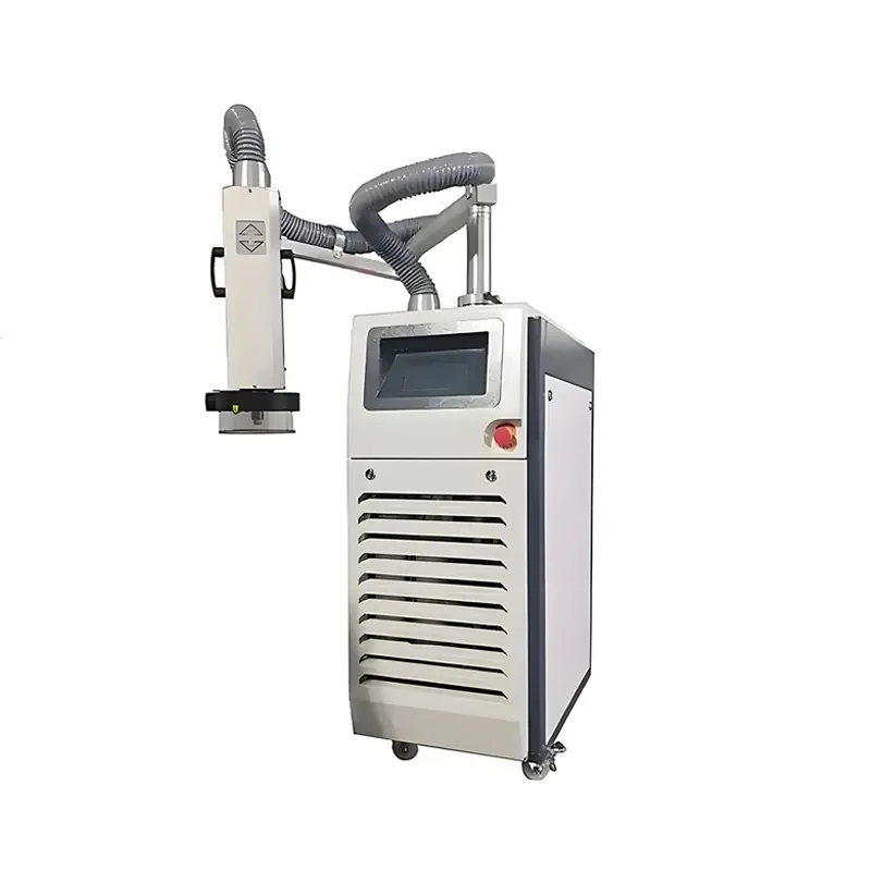
The DERUI semiconductor temperature forcing system delivers a controlled hot or cold air stream directly to a device under test. It supports fast characterization of ICs, memory, PCBs, optical modules and 5G components while the DUT remains connected to electrical test equipment.
This Is a Temperature Forcing System—not a Heat Flux Meter
A heat flux meter measures heat-transfer rate per unit area. This equipment instead creates and controls a localized thermal environment around a DUT. The technically correct search terms are temperature forcing system, thermal stream or thermostream system.
IC Characterization
Measure functional and electrical behavior at hot, cold and intermediate case-temperature conditions.
Memory and Storage
Test Flash, eMMC and related devices for startup, timing and data performance across temperature.
5G and Optical Modules
Condition SFP/transceiver modules, RF devices and communication boards while connected to ATE or a functional test setup.
Focused Hot and Cold Air Around the DUT
Generate the Air Stream
Mechanical refrigeration and electric heating condition the process air over the selected operating range.
Deliver Through a Nozzle
A hose, nozzle, shroud or thermal cap directs conditioned air around the package, socket, module or small assembly.
Stabilize and Test
The control system holds the selected condition while electrical instruments measure function, timing, power or failure behavior.
Unlike a full temperature test chamber, a forcing system conditions only the target region. This reduces thermal mass and can shorten characterization time while leaving probes and test connections accessible.
Temperature Forcing System Specifications
| Stated air-temperature range | −65°C to +225°C |
|---|---|
| Stated hot/cold changeover | −55°C to +125°C in 13 seconds |
| Temperature control accuracy | ±1°C stated; control point and test condition to be confirmed |
| Display resolution | 0.1°C |
| Maximum air flow | 18 SCFM (approximately 30.6 m³/h) |
| Cooling method | Mechanical refrigeration; no liquid nitrogen stated |
| Moisture management | Defrost function stated for removal of accumulated moisture |
| Controls | Mobile design with touchscreen human-machine interface stated |
What Determines Time to Stabilization?
- Package dimensions, material and thermal mass
- DUT power dissipation and operating mode
- Socket, PCB and fixture thermal paths
- Nozzle distance, shroud leakage and conditioned-air flow
- Feedback sensor type, location and attachment
- Required stability band and dwell rule
Case Temperature Is Not Junction Temperature
A thermocouple near the package measures a local surface or air condition. Junction temperature may differ because of device power and junction-to-case thermal resistance. If junction behavior is critical, define the electrical or model-based method used to estimate or control it.
Prevent Condensation During Cold Testing
When a DUT surface falls below the ambient dew point, moisture can condense on the device, socket and PCB. A suitable enclosure or shroud, dry process air, purge sequence and controlled warm-up are important for electrical safety and repeatability.
Interface Kit
Confirm hose length, nozzle, thermal cap/shroud, fixture opening, sensor and mounting hardware for the actual DUT. A poor seal increases air demand and slows stabilization.
Defrost Strategy
The stated defrost function addresses moisture accumulation inside the thermal system. It does not eliminate the need to manage condensation at the DUT and test fixture.
Information Required Before Configuration
DUT and Fixture
Package/module dimensions, socket, board layout, exposed area, sensor position, cable access and allowable force.
Thermal Profile
Air or case-temperature target, transition direction, stabilization tolerance, dwell, cycles and intermediate points.
Operating Load
DUT power at each condition, maximum transient power and whether power changes during the electrical test.
Laboratory Utilities
Supply voltage, compressed/dry-air requirement, heat rejection, exhaust, noise limit and available floor/bench space.
Integrating Thermal Stream with ATE
Characterize the Setup
Verify sensor placement, shroud sealing and the relationship between air, case and any estimated junction temperature.
Run the Sequence
Command the target, wait for the agreed stabilization rule, execute the electrical test and record temperatures with results.
Return Safely
Warm the DUT above the condensation-risk point before opening the shroud or removing it from dry-air protection.
Semiconductor Temperature Forcing System FAQs
What is a semiconductor temperature forcing system?
It delivers controlled hot or cold air to a localized DUT so electrical behavior can be measured at selected temperatures without conditioning a full chamber.
Is it a heat flux meter?
No. It does not primarily measure heat flux in W/m². It is a thermal-stream source and temperature-control system.
Does the DUT reach −55°C to +125°C in 13 seconds?
Not necessarily. The figure describes the stated air transition. DUT stabilization depends on thermal mass, power, fixture, airflow, sensor and tolerance.
Why use it instead of a temperature chamber?
It provides faster localized conditioning and easier access to probes, sockets and ATE, making it useful for device characterization and failure analysis.
Can it control junction temperature?
Directly controlling junction temperature requires a suitable electrical sensing or thermal model. Standard setups more commonly control air or package-case temperature.
Does it require liquid nitrogen?
The supplied specification states mechanical refrigeration without LN₂. The system still contains a closed refrigeration circuit; refrigerant type and service details should be confirmed.
How is condensation prevented?
Use dry conditioned air, a well-sealed shroud, controlled purge and warm-up, and keep the DUT protected until it is above the ambient dew point.
What should I send for selection?
Provide DUT/fixture drawings, power dissipation, target temperature, sensor/control point, transition and stability requirements, test sequence and laboratory utilities.
Configure the Thermal Stream Around Your DUT
Send DERUI your device, socket and fixture drawings, power dissipation, temperature profile, feedback method and ATE sequence. We will review the nozzle/shroud, airflow and control configuration.