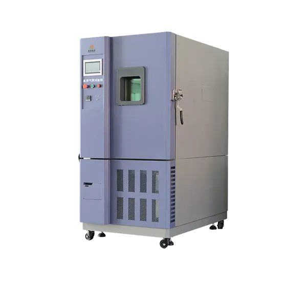
DR-H203-100
100L Temperature Shock Test Chamber
The DERUI DR-H203-100 uses switched hot and cold airflow around a stationary specimen area. It is intended for component and assembly tests where specimen movement or connected cables make basket transfer unsuitable. Define the exposure sequence, load and recovery criterion before selecting the chamber configuration.
DR-H203-100
What This Chamber Is Designed to Verify
Temperature shock testing exposes defects driven by unequal thermal expansion and contraction. It can support screening and qualification work on electronic components, automotive electrical parts, material assemblies and similar specimens when the selected cycle matches the governing test plan.
Thermal mismatch
Rapid temperature change can load solder joints, interfaces, coatings, seals and bonded materials at different expansion rates.
Intermittent faults
Electrical connections and assemblies may be monitored before, during or after cycling when the test method and chamber interfaces permit it.
Process screening
Repeated hot-cold exposure can help compare manufacturing lots or design revisions, but pass/fail criteria must come from the product specification.
DR-H203-100
DR-H203-100 Configuration
Use the model baseline below for configuration review. It is not a universal guarantee for every specimen load.
| Item | Specification | Quotation check |
|---|---|---|
| Model / capacity | DR-H203-100 / 100 L | Confirm usable specimen envelope and internal dimensions |
| Hot-zone range | +60°C to +150°C | Confirm required high setpoint and dwell |
| Cold-zone options | 0°C to -40°C or 0°C to -55°C | Select the required low-temperature configuration |
| Heat-storage pull-up | Room temperature to +180°C within 35 min | Zone preparation value; not specimen transition time |
| Cold-storage pull-down | Room temperature to -55°C within 60 min | Confirm ambient and empty/loaded condition |
| Temperature conversion | 2–10 s | Confirm how transfer is defined and verified |
| Recovery and stabilization | 5 min | Confirm sensor point, tolerance and load condition |
| Power supply | AC380V, 50/60Hz, three-phase | Confirm site voltage, frequency, current and protection |
| Controller | 7-inch or 10-inch LCD touchscreen; Chinese/English | Confirm data, program and communication functions ordered |
DR-H203-100
How the Three-Zone Air-Door System Works
Condition the hot and cold zones
The preheating and precooling chambers reach their programmed conditions before exposure begins.
Switch the airflow path
A pneumatic cylinder actuates the insulated SUS304 air door so conditioned air from the selected zone reaches the stationary specimen chamber.
Recover and dwell
The system is evaluated against the agreed recovery tolerance before the specified dwell and next transition are completed.
DR-H203-100
Construction, Control and Safety
Chamber construction
construction includes a 1.2 mm SUS304 interior, 1.2 mm powder-coated cold-rolled-steel exterior, glass-fibre and rigid polyurethane insulation, and separate doors for the hot, cold and specimen zones.
Fixture and interfaces
Two adjustable SUS304 grid shelves are listed at no more than 25 kg each, with 40 mm adjustment spacing and a Φ50 mm cable port on the left side.
Control and protection
The page lists programmable touchscreen control, PT100 sensing, PID/SSR regulation, RS-232, protection for overtemperature, phase/voltage, compressor pressure and overload, leakage and pneumatic operation.
DR-H203-100
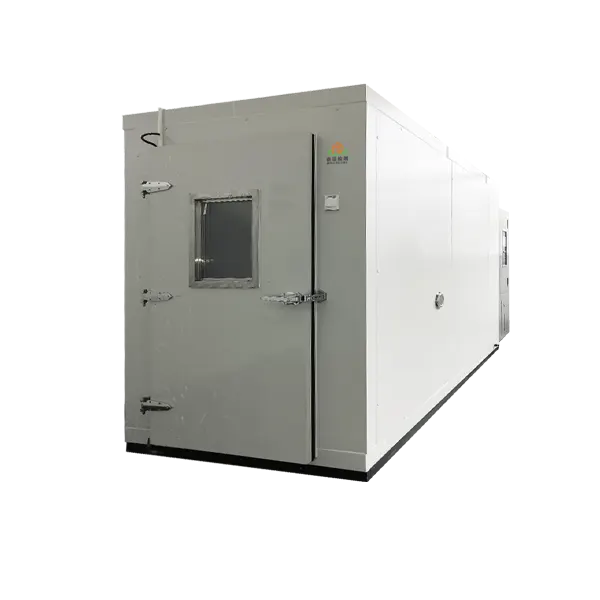
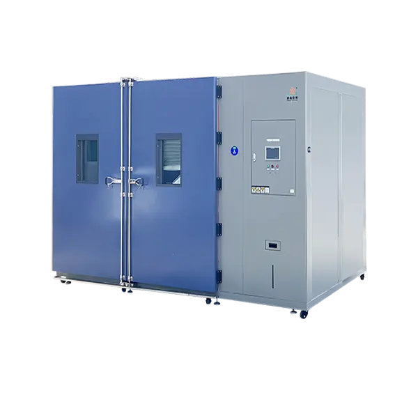
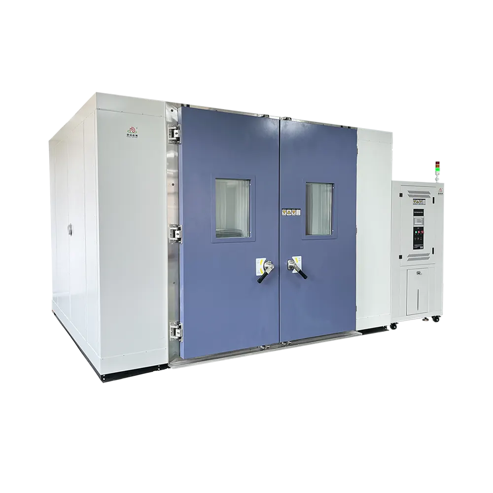
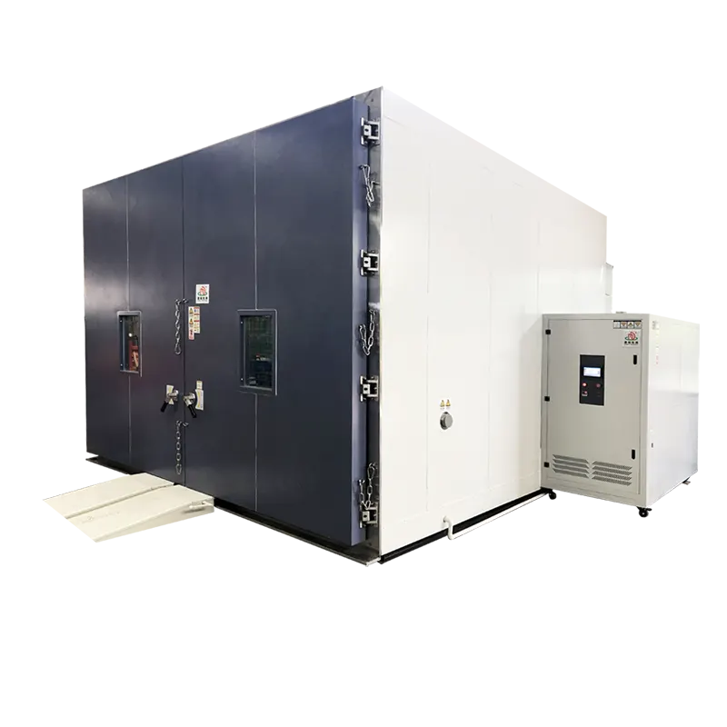
DR-H203-100 Product View
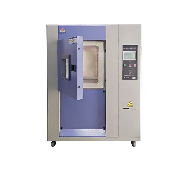
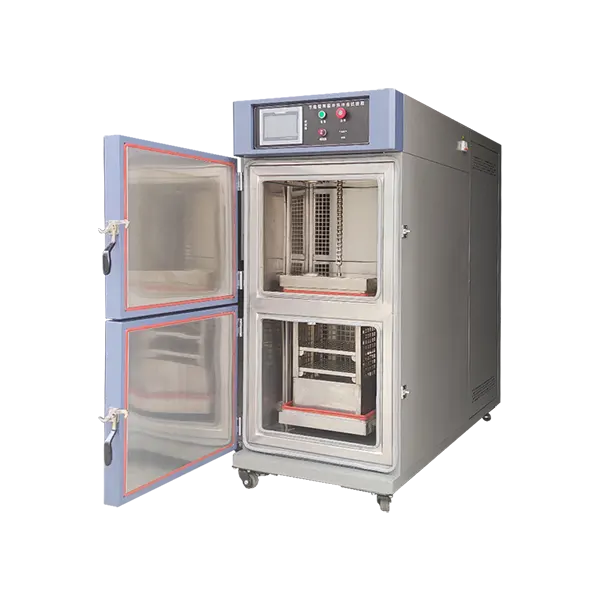
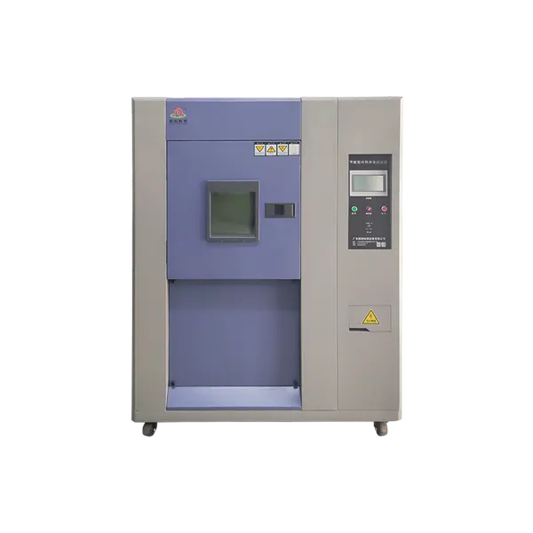
DR-H203-100 product view. Door arrangement, controller, cooling method and connection layout follow the approved configuration.
DR-H203-100
Map the Test Method to the Required Cycle
IEC 60068-2-14:2023 covers change-of-temperature tests, while MIL-STD-810H Method 503.7 addresses temperature shock through a tailored test programme. The chamber does not create compliance by itself; the edition, procedure, temperature extremes, dwell, transfer and specimen response criteria must match the test plan.
| Test-plan input | What to define | Why it changes the chamber selection |
|---|---|---|
| Specimen | Dimensions, mass, quantity, fixtures and orientation | Determines usable space, airflow restriction and thermal response |
| Temperature cycle | Hot/cold setpoints, tolerance, dwell and cycles | Defines stored hot/cold capacity and programme duration |
| Transfer and recovery | Maximum conversion time, recovery tolerance and measurement point | Separates air-door action from chamber-air and specimen response |
| Powered operation | Heat dissipation, cable count, signals and monitoring | Affects cooling load, port sealing and data requirements |
| Acceptance | Empty/loaded condition, sensors, records and report format | Creates measurable FAT criteria |
DR-H203-100
Temperature Shock vs Adjacent Chamber Types
Temperature shock chamber
Uses separate conditioned zones and rapid switching to impose abrupt ambient changes. Select it when transfer severity is part of the method.
Rapid temperature change chamber
Changes one workspace at a controlled ramp rate without switching between stored hot and cold zones. It serves a different thermal profile.
Temperature-humidity chamber
Controls longer climatic profiles and moisture exposure. Humidity is not a verified DR-H203-100 thermal-shock function and is excluded from this configuration.
DR-H203-100
Recommended FAT and RFQ Checklist
| Check | Information or verification |
|---|---|
| Specimen fit | Usable W × D × H, mass, shelf loading, airflow clearance and cable routing |
| Zone preparation | Hot/cold setpoints, pull-up/pull-down condition and stabilization |
| Cycle performance | Air-door conversion, recovery, dwell, cycle count and sensor locations |
| Utilities | Voltage, frequency, cooling method, compressed air if required, ambient limits and installation access |
| Controls | Programme capacity, alarms, communications, data export and powered-specimen interfaces included in the quotation |
| Documents | Approved drawing, bill of materials, operating manual, electrical schematic, FAT record and calibration scope |
DR-H203-100
Plan the purchase around your specimen and laboratory
For the buyer
Start with the specimen and its external connections. A stationary workspace can simplify monitoring, but the quote must identify usable space, shelf arrangement, cable-port sealing and the purchased control interfaces. Ask whether the selected cycle includes only hot/cold exposure or also an ambient step; a three-zone construction label alone does not define the programme.
For the test engineer
For a wired automotive electronics assembly, map the cables, connectors, sensor leads and any powered heat before loading the chamber. Keep feedthroughs from obstructing the switched airflow path. Agree whether functional testing runs continuously or only after stabilization, and which data must be synchronized with the thermal record.
Evidence before approval
Use the FAT to verify air-door sequence, hot/cold storage readiness and recovery at agreed monitoring points. If specimen response matters, attach agreed sensors to representative parts and record those channels alongside chamber air. An air-door actuation time alone does not demonstrate that the complete assembly has reached the target temperature.
DR-H203-100
Select the architecture that matches the test
50L Thermal Shock Testing Chamber · Two-Zone Thermal Shock Test Chamber
Compare the 50L option for smaller specimen packages and the 80L two-zone design when basket movement is acceptable. Check the achieved profile and connection arrangement, not volume alone.
Thermal shock equipment category · Rapid temperature change chamber · Temperature test chambers
Request a configuration review
Send the specimen and fixture drawing, quantity, mass, powered heat, temperature sequence, monitoring requirements and laboratory utilities. Include the governing method, acceptance criteria and destination so the proposed build and any open requirements can be reviewed before quotation.
Review DERUI company information and qualification documents. Ask which documents cover the proposed equipment and configuration.
Keep electrical connections accessible during exposure
The stationary specimen arrangement suits boards and assemblies that remain connected to external instruments. Plan the left-side cable route, feedthrough sealing, service loop and fixture support before fixing the rack layout. Leave clearance around the specimen so switched airflow reaches the surfaces under test.
Specify shelves, feedthroughs, monitoring channels and any powered-test interlocks in the supply schedule. Check the door sequence and air recovery with the representative thermal load. A shelf load rating establishes mechanical support, not recovery performance for that mass.