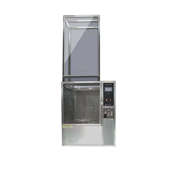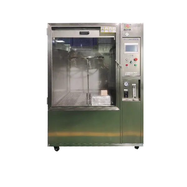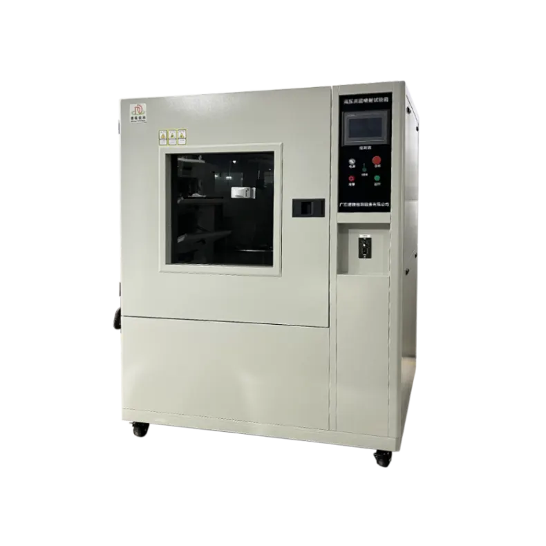


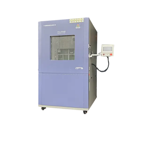

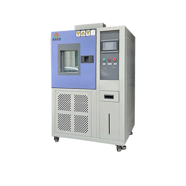
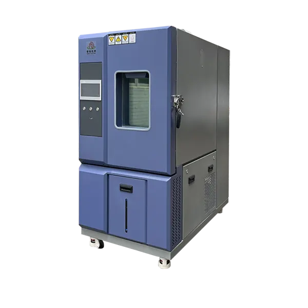
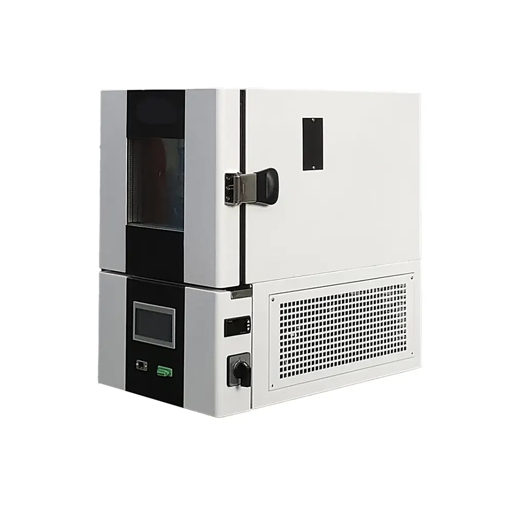
Put Enclosure Seals Through a Defined Hot-Water Jet Exposure
Evaluate joints, cable entries and connectors exposed to close-range pressure washing. The DERUI IPX9K test chamber combines four spray angles with a rotating specimen table, an 8–10 MPa water-pressure range and 14–16 L/min flow. Select the setup around your assembly and required test method—not the cabinet size alone.
Choose an IPX9K Chamber for the Exposure Your Product Faces
Target the vulnerable interfaces
Hot-water jets challenge enclosure seams, gasket interfaces, connector seals and cable glands. A rotating specimen presents different surfaces to the spray; the fixture must keep the assembly stable without shielding an opening or compressing a seal more than its normal installation would.
Typical applications include vehicle lighting, sensors, control units, motors and other electrical housings with a specified high-pressure wash-down requirement. Battery-related enclosures may also require this exposure, but cell or pack safety testing is a separate scope.
For development work, retain the same assembly state and setup when comparing seal designs. For qualification, use the specified preconditioning, exposure and post-test checks. An application name alone does not establish the correct test procedure.

IPX9K, IPX9 and IP69K: Define the Requirement Before Ordering
| Designation | What it means for equipment selection |
|---|---|
| IPX9K / ISO 20653 | Road-vehicle water-protection procedure. Specify edition, clause and any OEM additions. |
| IPX9 / IEC 60529 | A distinct enclosure water-jet procedure. Verify the installed setup against that method before making a capability claim. |
| IP69K | A combined dust and water designation for the specimen; this hot-water chamber does not replace dust-test equipment. |
ISO 20653:2023 addresses road-vehicle enclosure protection. Its revision includes changes to IPX9K conditions and jet impact-force measurement. IEC 60529 provides the separate enclosure IP-code framework. Purchase specifications should identify the adopted document rather than use “IPX9K compliant” as a complete test plan.
IPX9K Chamber Technical Configuration
| Parameter | Configuration |
|---|---|
| Internal workspace | 800 × 800 × 800 mm; geometric volume 512 L |
| Approximate external dimensions | 1280 × 980 × 1650 mm |
| Specimen turntable | Ø400 mm; adjustable 4–10 rpm; rated load 50 kg |
| Suggested specimen envelope | ≤400 × 300 × 300 mm; check fixture and rotating clearance |
| Spray angles | 0°, 30°, 60° and 90° |
| Water spray pressure | 8–10 MPa (80–100 bar; 8,000–10,000 kPa) |
| Water flow | 14–16 L/min |
| Water temperature | Up to 80°C; specify required test temperature and tolerance |
| Adjustable nozzle distance | 100–200 mm; operating distance selected for the adopted method |
| Electrical supply / connected load | AC 380 V / 10.0 kW; destination frequency and connection specified in the proposal |
| Preliminary installation footprint | At least 2000 × 1200 mm is listed; add required access and service clearances |
| Water supply | Purified water preferred; external tap-water connection subject to water-quality review |
Cabinet volume is not usable specimen capacity. Final selection depends on the nozzle-to-surface distance, rotating specimen envelope, fixture mass and connected cables. The required exposure settings, measurement locations, tolerances and acceptance checks belong in the technical specification.
Does Your Complete Assembly Fit the Spray Arrangement?
Rotating clearance
Review the full swept envelope, including brackets, protruding connectors and cable bends. A rectangular assembly can extend beyond its nominal width as it turns.
Nozzle distance
The listed adjustment is 100–200 mm. Check the distance to the relevant specimen surface at each required angle; distance to the table center is not automatically distance to the enclosure.
Combined load
Review the specimen and fixture together against the 50 kg table rating. Include center of gravity, eccentric loading and secure mounting in the loaded-rotation check.
Keep the fixture from changing the sealing result
Clamps should not close an otherwise exposed gap, support plates should not block required spray access, and cables should not redirect water away from a gland. Document mounting orientation and connection details so the same setup can be reproduced.
For multiple specimens, confirm spray access to every unit and check whether the method permits the arrangement. Fitting several parts in a 512 L cabinet does not show that each receives the required exposure.
For a useful fit review: send an assembly drawing or photographs with dimensions, total mounted mass, mounting orientation and all external connections. Identify the surfaces and seals that the test must expose.
Verify the Jet at the Test Setup—not Only at the Pump
| Variable | What to define and verify | Why it matters |
|---|---|---|
| Pressure and flow | Measurement point, operating range, calibrated instruments and values during spraying | A setpoint or idle pump reading does not describe the complete operating exposure. |
| Water temperature | Required temperature, tolerance and measurement location throughout the sequence | Tank indication alone may not establish the water condition at the specified reference point. |
| Nozzle and impact | Nozzle geometry, condition, alignment and method-required impact-force checks | A worn or obstructed nozzle can change the jet even when supply pressure appears normal. |
| Motion and timing | Loaded table speed, angular coverage, nozzle sequence and exposure time | Machine adjustment ranges are not substitutes for the prescribed operating settings. |
| Distance and support | Specimen surface reference, fixture drawing and clearances at each angle | Incorrect geometry or shielding can leave critical interfaces underexposed. |
Make spray verification part of factory acceptance
For a purchase referencing ISO 20653:2023 or an IEC IPX9 procedure, agree the required impact-force measurement arrangement and documentation. Define whether the verification apparatus is included, supplied separately or used during acceptance. It is a method-specific requirement, not a feature to infer from the pump rating.
Record the selected pressure, flow and temperature while the agreed sequence runs. Include instrument IDs, calibration status, nozzle settings, table speed, test duration and photographs of the actual fixture. If timestamped logging or export is required, state channel coverage, sampling interval and file format in the proposal.
Water System, Installation and Safe Operation
Plan the water and heating duty
Define the number of consecutive tests, exposure duration and turnaround needed by your laboratory. Heating capacity, water volume and replenishment conditions affect the ability to maintain the required temperature during repeated runs.
Purified water is preferred in the listed configuration. Review hardness and suspended solids before using tap water. Agree filtration, water replacement, draining and heater descaling requirements. If recirculation is required, include tank capacity, contamination control and service access in the configuration review.
Plan access, utilities and protection
The machine is listed at AC 380 V and 10.0 kW. Confirm frequency, phase arrangement, protective earth, breaker and cable requirements from the electrical documentation. The listed 2000 × 1200 mm venue footprint is a starting point, not a complete service-clearance plan.
High-pressure hot water creates burn, injection, electrical and stored-pressure hazards. Specify door interlocking, over-temperature protection, low-water protection, emergency shutdown and safe depressurization in the safety scope. Demonstrate the agreed functions during acceptance; never bypass protection during operation.
Powered specimens need a separate interface plan
Provide operating voltage, maximum load, duty cycle and monitored signals. Specify protected feed-throughs, cable routing, permissible connections and shutdown behavior. A cable interface must maintain spray containment without sealing or shielding the specimen in a way that changes its test exposure.
From Test Setup to an Interpretable Result
- Identify the procedure. Record standard edition, clause, OEM instructions, exposure settings and acceptance criteria.
- Prepare the specimen. Document seals, fasteners, preconditioning, installation orientation and powered state.
- Verify the exposure. Check water conditions, spray geometry, method-required impact verification, loaded table speed and timing.
- Run the defined sequence. Record settings and interruptions. Apply the governing procedure’s rules for interrupted tests rather than silently extending or repeating exposure.
- Open and inspect safely. Depressurize and control hot-water hazards. Follow the specified handling sequence so residual external water does not distort the ingress assessment.
- Evaluate against the product requirement. Apply the required ingress, functional, insulation or visual checks and retain the associated record.
A successful machine cycle is not automatically a passing product result. The exposure record establishes what the specimen experienced; the post-test evaluation establishes whether it meets the agreed requirement.
Agree the Evidence You Need Before Delivery
| Acceptance area | Evidence to define in the purchase specification |
|---|---|
| Specimen fit | Representative assembly or agreed dummy load, fixture drawing, clearance and loaded table operation |
| Exposure performance | Measured water pressure, flow, temperature, geometry, timing and applicable jet verification |
| Safety and interfaces | Agreed interlock/protection checks, shutdown and depressurization sequence, sample-interface review |
| Records | Channel list, logging/export scope if required, instrument identification and agreed test-report format |
| Handover | Operating manual, maintenance schedule, utilities drawing, calibration scope and factory acceptance record |
If you need third-party witnessing or calibration, specify the organization, measurement scope and report requirements before quotation. Define which tests are performed at the factory and which are repeated after installation at your laboratory.
Select Different Equipment for Different Water Exposures
| Required exposure | Relevant DERUI equipment |
|---|---|
| Spraying and splashing water | IPX3 / IPX4 oscillating-tube rain spray chamber |
| Water jets | IPX5 / IPX6 water-jet chamber |
| Water immersion | IPX7 / IPX8 immersion test chamber |
| High-pressure hot-water jets | This IPX9K chamber, with a method-matched nozzle, specimen and verification arrangement |
Compare the complete rain and water-ingress test equipment range if your test programme includes more than one exposure. For a combined dust/water designation, review the separate dust test chamber range.
IPX9K Test Chamber FAQ
What is the difference between IPX9K and IPX9?
ISO 20653 uses K-designations for road-vehicle enclosure protection; IEC 60529 includes an IPX9 water-jet procedure. Specify the standard edition and clause before selecting the apparatus. Review nozzle geometry, exposure conditions, specimen arrangement and verification requirements for that procedure rather than treating the labels as interchangeable.
Does this chamber provide IP69K certification?
The chamber performs the specified water exposure; it does not certify a product. IP69K includes both a dust-protection designation and a water-protection designation. Dust testing requires a separate apparatus and procedure. Product approval depends on all applicable tests and their acceptance criteria.
Can an 800 mm chamber test an 800 mm specimen?
Not in this configuration. The listed specimen guideline is up to 400 × 300 × 300 mm, with a Ø400 mm table. The rotating assembly, fixture and cables must also clear the nozzles while maintaining the required spray distance. Send the complete mounted assembly for a fit review.
Does the 4–10 rpm range mean any speed is acceptable?
No. It describes the machine’s adjustment range. The actual speed, exposure duration and nozzle sequence must follow the adopted method. Factory acceptance should check the selected operating speed under the agreed specimen and fixture load.
Is a pressure reading sufficient to validate the jet?
No. Flow, water temperature, nozzle condition, spray geometry and distance affect exposure. Include the method-required jet impact-force verification where applicable, with the measurement arrangement and evidence defined in the acceptance plan. A pump-pressure display alone is not proof of the required exposure.
Can the specimen operate during testing?
Powered testing requires a specified electrical interface, protected cable routing, permitted load, monitoring and shutdown arrangement. Include the operating state and connector drawing with your inquiry. Do not assume a specimen supply or feed-through is included merely because the chamber itself uses AC 380 V.
Can it also test IPX5/IPX6 or IPX7/IPX8?
Not with the IPX9K spray circuit alone. Jet and immersion procedures use different apparatus and exposure conditions. Specify each required method so the proposal can identify separate equipment or explicitly engineered additional functions.
What data and calibration documents should be requested?
Specify the required channels, sampling interval, timestamps, file format and report contents. Agree instrument identification, measurement locations, calibration evidence and the factory acceptance record. Automatic logging, export and third-party inspection must be included explicitly in the selected configuration.
Match the Chamber to Your Enclosure and Test Method
Send your assembly details and required procedure. Request an IPX9K proposal covering specimen fit, spray conditions, interfaces and acceptance evidence—not just a cabinet price.
Start with these project details
- Standard edition, clause and customer procedure
- Specimen drawing, mounted dimensions and mass
- Powered state, connections and required monitoring
- Exposure sequence, records and acceptance needs
- Destination voltage/frequency, water and drainage