
Walk-In Rain Test Chamber for Large Assemblies and Multi-Face Spray
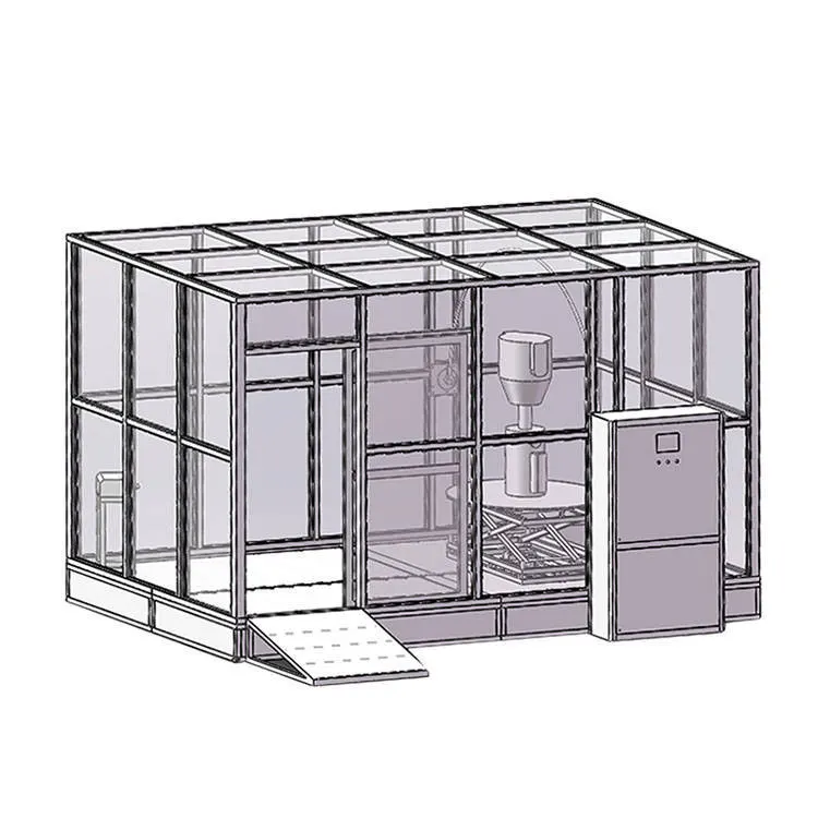
Test the weather resistance of a large enclosure or complete assembly without reducing it to a small coupon. The DERUI DR-H506 walk-in rain test chamber provides a published 7000 × 4000 × 4000 mm working area, with front-upper and side/top rain-intensity references for planning the exposure.
Build the test around the faces, joints, vents and interfaces that matter to your product. Define the loading arrangement, rain recipe, water circuit and evaluation criteria together so the quotation describes a usable test system—not only a room size.
Keep the Complete Assembly in Its Test Orientation
A large assembly can have several water-entry paths: door seals, cable entries, ventilation openings, panel joints and interfaces between components. A room-scale setup lets you plan exposure around the assembled product and its mounting orientation, rather than assuming that one small enclosure test represents every joint.
Use the DR-H506 as a project basis for large equipment housings, automotive assemblies and other specimens whose envelope or fixture makes a cabinet arrangement impractical. Provide the product drawing and the surfaces requiring exposure; suitability depends on the test method, loading arrangement and water delivery—not on the industry label alone.
Check the clear door opening and handling route separately from the internal working area. Include fixture width, lifting or trolley clearance, supports and access to inspection points. Floor capacity and wheel or point loads must be specified for the actual handling arrangement.
This is a rain-exposure product. It is not interchangeable with a temperature-humidity walk-in chamber, and chamber size does not establish an IP rating. Select the exposure configuration for the adopted procedure and assess the specimen against its agreed acceptance criteria.
Specify Rainfall, Water Pressure and Nozzle Geometry Separately
Rain intensity
The published references are (6 ± 1) mm/min at the front-upper area and (8 ± 1) mm/min at the side/top areas. Define where rain is collected, the collection interval and the specimen arrangement used to verify the selected exposure.
Water delivery
The published water-supply pressure is 150 ± 10 kPa. Pressure and flow help describe the water circuit, but neither alone proves the rainfall reaching every target surface. Include the measurement locations and operating nozzle groups.
Spray arrangement
The rain-nozzle diameter reference is 2.5–3.0 mm. One IPX5 and one IPX6 nozzle are also listed separately. Do not apply the rain-nozzle dimensions to those jet nozzles or substitute a rainfall intensity for a method-specific jet requirement.
Map the exposed faces before defining the pipe and nozzle layout. A tall fixture can shield a lower joint; a roof overhang can shelter a side opening; supports can redirect water toward areas that would not receive it in the intended service orientation. Review these effects with the specimen installed, not only in an empty room.
For a repeated production or development test, document the nozzle groups, specimen position, operating settings and exposure duration. If you change the fixture or product orientation, review whether the same recipe still exposes the intended surfaces.
IEC 60529 defines degrees of protection provided by enclosures. When requesting an IPX5 or IPX6 test setup, identify the adopted edition and agree the complete method conditions, including nozzle arrangement, flow, distance, exposure and evaluation. Supplied nozzles alone do not establish compliance.
DR-H506 Rain Test Room Configuration
Use these configuration references to define the ordered equipment and exposure schedule. Loading clearances, water delivery and acceptance conditions should be specified together with the room layout.
| Item | Configuration reference | Selection / acceptance condition |
|---|---|---|
| Model | DR-H506 | Walk-in rain test room configuration. |
| Working area (D × W × H) | 7000 × 4000 × 4000 mm | Confirm usable exposure zone, clear door opening and loading route in the project drawing. |
| Rain-nozzle diameter | 2.5–3.0 mm | Rain-spray reference; separate from the listed IPX5/IPX6 jet nozzles. |
| Spray-layout reference | 550 × 550 mm | Define nozzle positions and effective exposure in the approved layout. |
| Water-supply pressure | 150 ± 10 kPa | Define measurement location, active nozzle groups and operating flow. |
| Front-upper rain intensity | (6 ± 1) mm/min | Agree collection locations, measurement interval and loading arrangement. |
| Side/top rain intensity | (8 ± 1) mm/min | Agree the target faces and verification arrangement. |
| Pressure measurement | Class 1.5 gauge; 100 mm dial; 0–6 kg/cm² scale; pressure sensor | Specify instrument location and calibration/verification requirements. |
| Flow measurement | Electromagnetic flowmeter | Select range and installation for the required delivery duty. |
| Rain measurement | Arrangement selected for the required delivery duty | Agree collection method, positions and reporting requirements. |
| Pipe sizing | Selected according to flow requirements | Coordinate pipe sizes with nozzle groups and the water circuit. |
| Water-system equipment | Water pump, drainage pump and filter | Define water supply, drainage, filtration and any recirculation arrangement. |
| Test duration | Adjustable | Specify the exposure recipe and required timing records. |
| Additional nozzle configuration | One IPX5 nozzle and one IPX6 nozzle | Agree the complete method-specific operating setup. |
| Electrical supply | AC 380V ±10%, 50Hz | Confirm phase arrangement, rated demand and destination wiring in the electrical schedule. |
Design the Water Path from Supply to Drain
For a large rain room, the water circuit is part of the test configuration. Establish the required total flow with the selected nozzle groups operating, then define the pump duty, pipe sizes, filtration and drainage. Include the facility supply and discharge arrangements in the site plan.
| Project question | Why it matters | What to include in the proposal |
|---|---|---|
| How is water supplied and collected? | Supply limitations and collection capacity can affect a long exposure. | Required supply flow, storage where applicable, collection and drainage arrangement. |
| Will water be recirculated? | Recirculation changes filtration, contamination and maintenance requirements. | Supplied circuit, filter specification, water-quality requirements and replacement schedule. |
| Where are pressure and flow measured? | A pump-side reading may not describe conditions at the active nozzles. | Instrument positions, operating nozzle groups and verification procedure. |
| How will the product be powered or monitored? | Wet exposure and electrical operation require a defined safety plan. | Operating state, connections, monitoring and project-specific protective measures. |
| How is the room installed and serviced? | Large doors, pumps and pipework need access beyond the working area. | Overall footprint, handling route, maintenance clearance and facility utilities. |
Keep water quality and filter condition in the operating plan. Restrictions or deposits can change water delivery even when the timer completes normally. Define routine checks for nozzles, filters, seals, instruments and drains in the handover instructions.
Specify the access procedure for a wet test environment. Entry, inspection and maintenance should follow an agreed safe shutdown and pressure-release procedure. If interlocks, alarms or emergency-stop functions are required, list their supplied scope and fault response explicitly. Do not infer them from the room format.
Verify the Exposure Before Judging the Specimen
Separate two questions: did the equipment deliver the agreed exposure, and did the specimen meet its acceptance criteria? A completed timer answers neither question by itself. Define factory and site checks that connect the water-delivery settings to the intended product surfaces.
| Check | Evidence to agree | Purpose |
|---|---|---|
| Mechanical and loading review | Dimensions, clear opening, fixture arrangement and floor-load specification. | Confirm the actual assembly can be handled and positioned as intended. |
| Water-circuit verification | Operating nozzle groups, pressure/flow readings and measurement points. | Establish the delivery conditions for the selected recipe. |
| Rain-distribution check | Collection positions, interval, measured intensity and loading arrangement. | Verify target-area exposure and identify shielding or unintended runoff. |
| Controls and protection checks | Timing, stop behavior and the ordered protective functions. | Confirm the agreed operating and fault-response scope. |
| Application trial | Specimen position, exposure record, inspection sequence and result criteria. | Make the trial repeatable and distinguish equipment acceptance from product results. |
Define when and how the product is inspected. Water on the exterior can enter during handling or opening, while some procedures require specific conditioning or functional checks. Follow the adopted method and test plan so the inspection does not introduce an unintended exposure.
Record the recipe, product and fixture identification, nozzle groups, water settings, exposure duration and observations. Specify the recording format and any required controller export with the quotation; a pressure sensor or flowmeter does not automatically imply downloadable time-stamped data.
For procurement, request a layout drawing, water-system schedule, utility requirements and a measurable acceptance plan. These make competing configurations easier to compare than a generic claim of “precise rainfall and humidity control.”
Walk-In Rain Test Chamber FAQ
What is the DR-H506 designed to test?
It is a walk-in rain test room configuration for large assemblies and enclosures requiring planned multi-face water exposure. Define the specimen orientation, target surfaces and adopted test method to select the arrangement.
What is the published working area?
The published working area is 7000 × 4000 × 4000 mm in depth × width × height. Confirm clear door dimensions, usable exposure space, fixture clearances and loading capacity in the project drawing.
How are rainfall and water pressure specified?
The listed references are (6 ± 1) mm/min at the front-upper area, (8 ± 1) mm/min at the side/top areas, and 150 ± 10 kPa water-supply pressure. Agree collection positions, measurement intervals, active nozzle groups and loading conditions for acceptance.
Does the supplied IPX5/IPX6 nozzle configuration guarantee an IP rating?
No. One IPX5 and one IPX6 nozzle are listed, but the complete operating setup and specimen assessment must follow the adopted procedure. Rain intensity and rain-nozzle diameter are not substitutes for the jet-test conditions.
Is a rain room the same as a temperature-humidity chamber?
No. Rain exposure and controlled chamber temperature/humidity are different functions. If your test requires combined climatic and water exposure, specify those conditions and obtain an explicitly configured system.
What information is needed for a quotation?
Send the assembly and fixture dimensions, mass and handling arrangement, target faces, required rain or jet method, exposure duration, powered operating state and site utilities. Include inspection criteria and required records to define the acceptance scope.
Request a Rain-Room Proposal for Your Assembly
Send the Product Drawing and Required Water Exposure
Tell DERUI what must fit inside, which faces need exposure and how the product will be operated and inspected. Request a proposal covering the loading layout, spray arrangement, water circuit, site utilities and acceptance records.
Comparing test formats? Review the rain and water-ingress equipment range for method-specific systems, or the walk-in chamber range for large-room applications. For immersion rather than spraying, see the IPX7/IPX8 immersion test chamber.