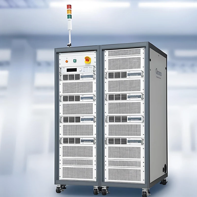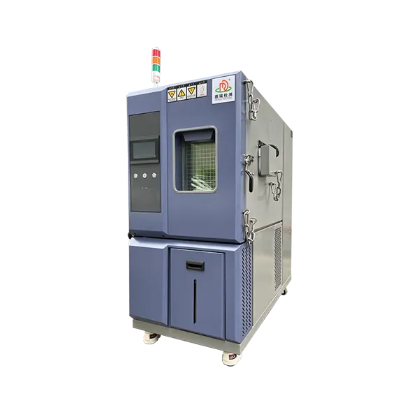


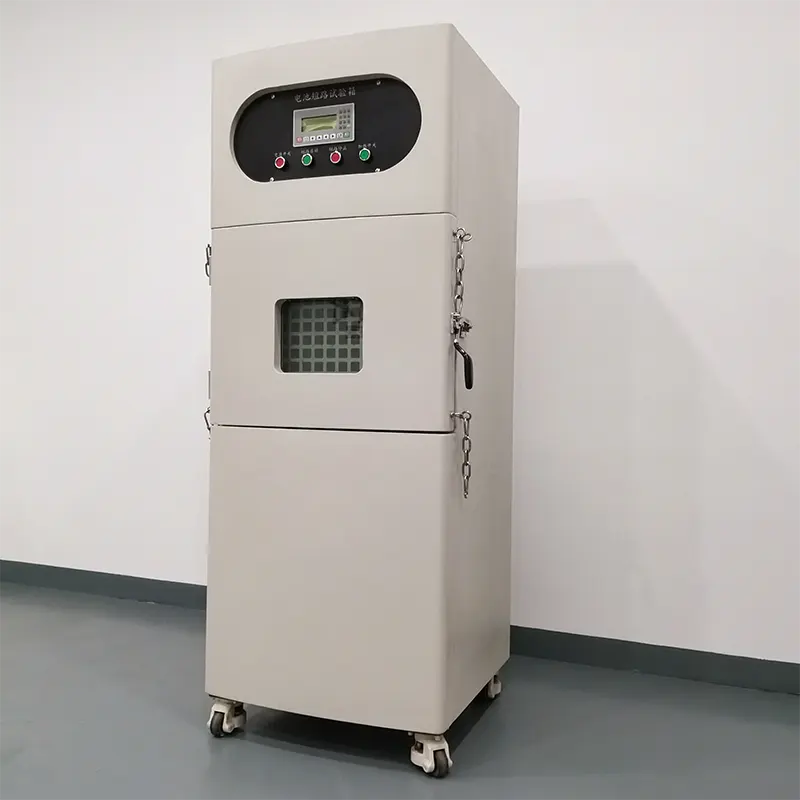
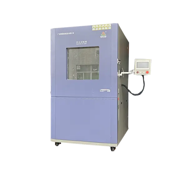

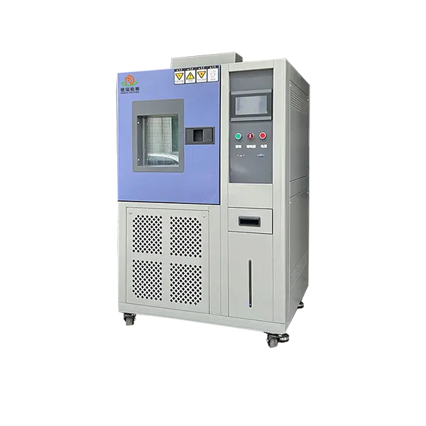
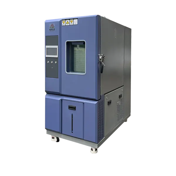
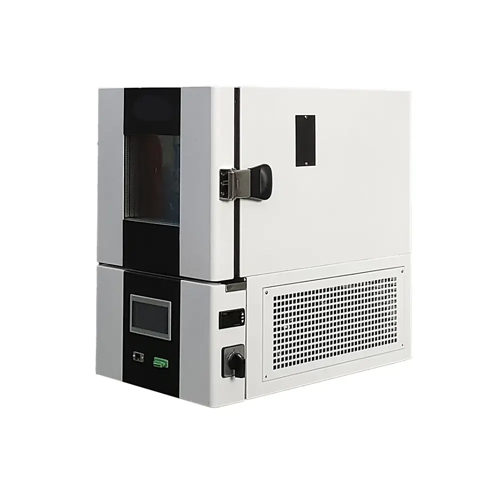
Controlled Temperature Testing for Battery Cells, Modules and Packs
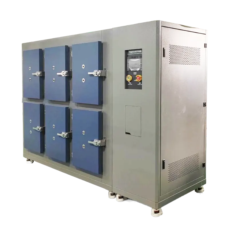
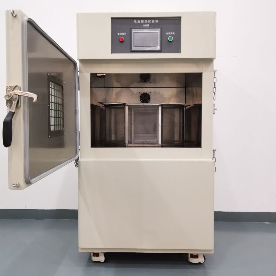
A battery temperature test chamber creates controlled hot, cold or programmed cycling conditions around the specimen. It can support development, verification and production-quality work when the chamber is matched to the complete battery load, operating state and governing test procedure.
Temperature range alone is not enough for selection. Battery mass, heat capacity, powered heat output, fixture layout and airflow restriction determine whether the loaded specimen can follow the required profile. Safety provisions must also match the cell chemistry, state of charge, energy and credible failure modes.
Direct answer: send the complete temperature graph and specimen information before selecting chamber volume or cooling capacity. If the method involves crushing, penetration, overcharge, external short circuit, fire exposure or thermal-runaway propagation, review the dedicated abuse-test equipment and facility separately.
Performance Data for Preliminary Configuration
The existing page does not identify a model or standard chamber volume. Treat these values as a preliminary performance description and reconfirm them against the selected size, cooling system and ordered safety package.
| Item | Current published value | Quotation requirement |
|---|---|---|
| Temperature range | −40°C to +100°C; −70°C stated as customizable | Confirm required extremes, working range and selected refrigeration system. |
| Heating rate, no load | 1°C/min; 5–25°C/min stated as customizable | Define start/end points, air or specimen basis, load and tolerance. |
| Cooling rate, no load | 1°C/min; 5–25°C/min stated as customizable | Define start/end points, ambient condition, load and cooling method. |
| Temperature uniformity | ≤±1°C, no load | Confirm workspace, sensor layout, setpoints and verification method. |
| Temperature fluctuation | ≤±0.5°C | Confirm the measurement convention and operating range. |
| Controller and sensor | Multi-segment fuzzy PID; 7-inch touch screen; PT100 Class A | Confirm programs, channels, alarms, permissions and required records. |
| Communication | TCP/RS485; CAN stated as customizable | Define protocol, data fields and connection to external cycler or DAQ. |
| Test port | One Ø100 mm port | Confirm cable quantity, connector size, sealing and thermal leakage. |
| Construction | SUS304 interior; coated cold-rolled-steel exterior | Confirm chamber size, shelves, floor load and battery fixtures. |
| Power | 380 V, 50 Hz | Final voltage, phase, current and breaker depend on configuration. |
Data correction required: the old page lists an observation window as “300 × 450 cm.” This is not credible for a chamber window and must be verified from the drawing before publication. The old generic claim of −60°C to +150°C also conflicts with the parameter table and has therefore not been retained.
Convert the Battery Test into a Complete Loaded Profile
The applicable battery, vehicle, transport or customer document determines the exposure. Do not copy a temperature sequence from another product without confirming specimen type, operating condition and edition.
Temperature storage
Unpowered specimens may be held at defined hot or cold conditions, followed by recovery and inspection.
- Starting condition
- Setpoint and tolerance
- Stabilization criterion
- Dwell and recovery
Operating-temperature test
Cells, modules or packs may operate, charge or discharge while temperatures change. External cyclers and monitoring interfaces become part of the setup.
- Current and voltage limits
- Heat output
- Cable routing
- Fault and stop conditions
Temperature cycling
Repeated high-low exposure requires a complete graph defining ramps, dwells, cycle count and when timing begins.
- Air versus specimen rate
- Loaded recovery
- Sensor locations
- Data and deviations
Match Safety Functions to the Battery Hazard
The existing page mixes standard protections with optional fire and pressure controls. The final design must come from a documented risk assessment, not a generic feature list.
Electrical and temperature protection
Define independent over-temperature limits, heater and refrigeration protection, overcurrent, overload, grounding and emergency isolation.
Event detection
Specify temperature, smoke, gas, pressure or video monitoring only where required, including alarm and shutdown logic.
Pressure and exhaust
Review credible gas release, relief path, ducting, treatment, room ventilation and safe discharge location.
Fire response
Define whether suppression, flooding, water, inert gas or another strategy is permitted for the specimen and facility.
Operator separation
Consider reinforced construction, door restraint, remote observation, access interlock and an exclusion zone according to test energy.
Important: pressure relief, fire suppression, gas detection and reinforced construction must not be presented as standard until the selected configuration confirms them. The chamber does not replace the laboratory emergency plan or local authority requirements.
Nine Inputs for Battery Chamber Selection
Governing method
Standard, edition, clause, customer document and deviations.
Specimen envelope
Dimensions, mass, quantity, orientation, spacing and fixtures.
Battery condition
Chemistry, capacity, state of charge and prior conditioning.
Complete profile
Start, extremes, ramp, stabilization, dwell, recovery and cycles.
Powered heat load
Charge/discharge current, changing heat output and external cycler.
Measurement basis
Air and specimen sensors, channel count, rate definition and records.
Safety package
Credible failures, detection, relief, exhaust, isolation and response.
Laboratory utilities
Power, cooling, drainage, ventilation, access and floor loading.
Acceptance evidence
Drawings, options, calibration, loaded demonstration and documents.
Loaded acceptance test: agree on specimen simulator or actual load, sensor positions, temperature points, ramp definition, tolerances, dwell, safety logic and exported records before manufacture is completed.
Battery Temperature Test Chamber FAQs
What temperature range should be selected?
Select from the required test extremes plus usable control margin, not from the widest catalogue range. Confirm the loaded profile, ambient conditions and selected refrigeration system.
Is 1°C/min the battery temperature-change rate?
No. The current page states a no-load chamber performance. Battery response depends on mass, heat capacity, airflow, fixture and powered heat output. Define the required measurement point and load.
Does this chamber control humidity?
The published parameter table does not confirm a humidity system. If temperature-humidity testing is required, specify the complete operating envelope, water system and dew/frost constraints as a different configuration.
Can batteries charge and discharge inside the chamber?
Yes only when the project includes suitable feedthroughs, external cycler interfaces, cable protection, electrical monitoring and agreed fault logic. Send current, voltage and heat-output data.
Are fire suppression and gas detection included?
They are not confirmed as standard by the parameter table. Select them through the project risk assessment and list the ordered safety hardware in the technical agreement.
What information is needed for quotation?
Provide the method, complete profile, battery drawing, mass, chemistry, state of charge, powered condition, heat output, fixtures, monitoring, hazards, utilities and acceptance requirements.
Configure the Chamber Around Your Battery Load
Send the temperature graph, battery drawing, state of charge, powered heat output, safety assessment and laboratory utilities.