


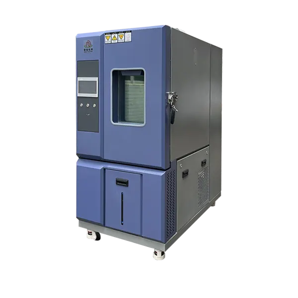
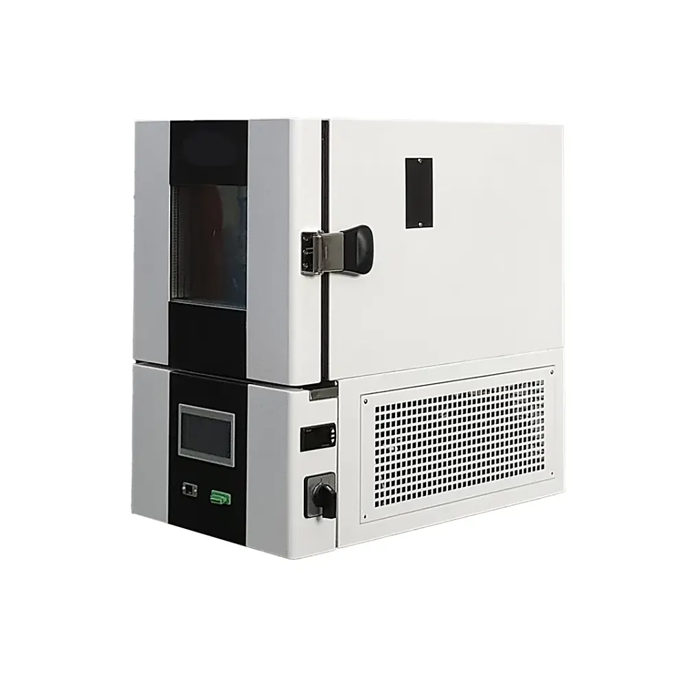
Battery Impact Test Chamber for 9.1 kg Drop Testing
Evaluate a defined gravity-impact event on a cell using an electrically raised, electromagnetically released 9.1 kg mass and a 15.8 mm crossbar. The enclosed system is intended for laboratories that need a repeatable drop setup and a documented, specimen-specific test plan.
What This Equipment Is Designed to Do
Set the impact geometry
Place the cell on the steel impact surface and position the specified crossbar across the specimen. Confirm bar material, length and orientation against the test document.
Control mass and height
Set the height, lift the mass electrically and release it through the electromagnet. The published range accommodates the 610 mm nominal setting used in certain impact procedures.
Observe within an enclosure
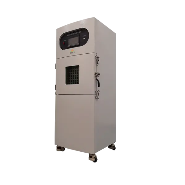
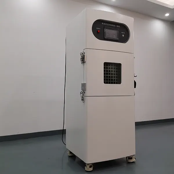
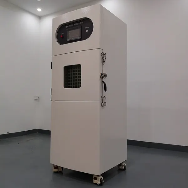
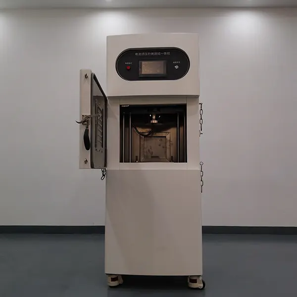
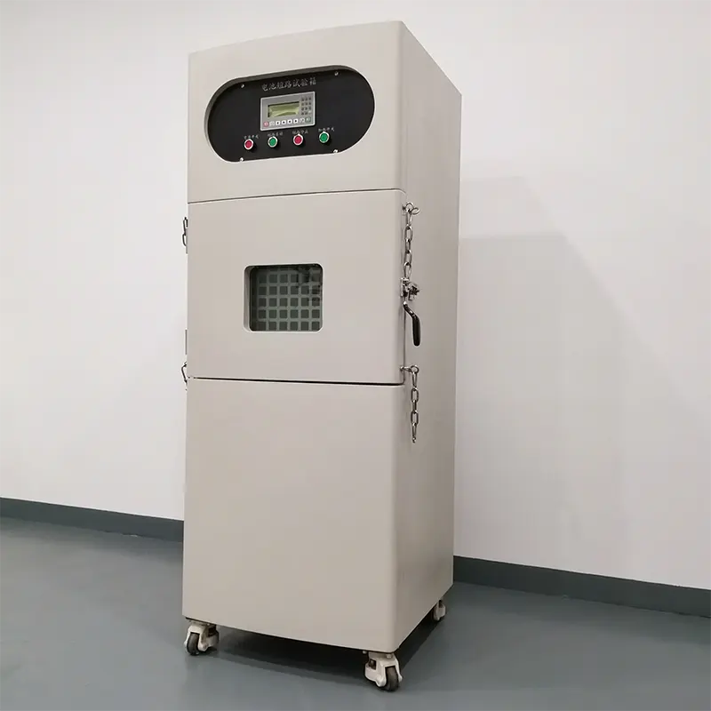
The cabinet includes an observation window and rear exhaust fan. The project-specific hazard assessment still determines ventilation, personnel exclusion and emergency response.
Published Technical Parameters
These are values published on the current DERUI product page. Confirm the final equipment drawing, test fixture and supplied documentation in the quotation.
| Parameter | Published value | Quotation or FAT check |
|---|---|---|
| Drop mass | 9.1 ± 0.1 kg | Mass identification and calibration record. |
| Drop height | 0–700 mm adjustable; height error ±5 mm | Reference point, physical height verification and repeatability at the intended setting. |
| Display precision | 0.1 mm | Display increment is not the same as ±5 mm height accuracy. |
| Crossbar | 15.8 ± 0.1 mm diameter | Material, length, straightness and orientation for the adopted procedure. |
| Controller and lift | PLC touchscreen; electric lifting | Setpoint, release sequence, door-state logic and event record. |
| Inner and outer panels | SUS304 stainless inner sheet 1.0 mm; painted cold-rolled outer sheet 1.0 mm | Final assembly construction and protective rating require separate evidence. |
| Window and door | 390 × 360 mm, 10 mm tempered-glass window; single door with lock | Do not infer a certified blast-containment rating from glass thickness alone. |
| Exhaust | Φ120 mm outlet with rear fan | Facility extraction, discharge route and treatment requirements. |
| Footprint and utilities | W940 × D780 × H1620 mm; AC220 V ±10%, 50 Hz; 2.0 kW; approx. 250 kg | Site access, power circuit, ventilation and service clearances. |
Define the Impact Procedure Before Testing
Select the exact method
Identify the standard edition, clause, eligible cell type and required sample count.
Prepare the specimen
Specify cell dimensions, state of charge, conditioning and identification in the approved plan.
Check the fixture
Verify bar material and size, cell support, placement and alignment before loading the mass.
Verify the height
Measure from the method-defined reference point and document the actual pre-release position.
Release and observe
Operate the release from a protected position and record event time, temperature and visible response using the agreed instrumentation.
Apply acceptance criteria
Judge the result under the adopted standard and record deviations; the chamber itself does not certify a cell.
UN 38.3 T.6: Capability Versus Test Compliance
UN Manual of Tests and Criteria, subsection 38.3.4.6, describes an impact route for specified cylindrical cells and a separate crush route for other cells. Its impact setup calls for a 9.1 ± 0.1 kg mass, a 15.8 ± 0.1 mm stainless-steel bar and a 61 ± 2.5 cm drop. The published equipment values cover the mass, diameter and adjustable height; bar material and length, guide behavior, specimen scope and the full procedure must be checked in the approved technical agreement.
Safety and Facility Integration
Enclosure is not a rating
The published steel cabinet and tempered observation glass describe physical construction, not a verified thermal-runaway or blast-containment class.
Exhaust needs a route
The Φ120 mm outlet and fan need a site-specific extraction design. Check expected gas, smoke and fire scenarios with the laboratory safety team.
Interlocks need verification
Confirm door interlock, emergency stop, release inhibit, remote observation and post-event access rules in the final configuration and FAT.
Recommended Factory Acceptance Checks
| Check | Witness evidence |
|---|---|
| Mass and bar | Measured mass, bar diameter, material and length; traceable instruments. |
| Height setting | Measured drop height at the agreed setting, including the reference point and stated tolerance. |
| Release path | Observed vertical fall, bar alignment, electromagnet release and retrieval sequence. |
| Control and safeguards | PLC display, door-state behavior, release inhibit and emergency-stop action as contracted. |
| Site interfaces | Electrical nameplate, exhaust connection, clearances and maintenance access. |
| Documentation | Drawing, manual, wiring, inspection record and calibration scope agreed before shipment. |
Frequently Asked Questions
Is this a UN 38.3 T.6 impact machine?
Its published mass, bar diameter and height range can support the impact geometry, but method suitability depends on the exact standard edition, eligible cell type, bar specification, guide and witnessed setup. Compliance cannot be concluded from three numbers alone.
Can it test pouch and prismatic cells under the same T.6 impact procedure?
Do not assume so. The UN 38.3 T.6 method distinguishes impact and crush routes by specimen scope. Review the applicable edition and use the correct apparatus for the selected route.
Does 0.1 mm display precision mean 0.1 mm drop-height accuracy?
No. The page separately publishes ±5 mm height error. Confirm the measurement reference and verification method at the intended height.
Does the window make the cabinet explosion-proof?
No certified containment rating has been verified from the published glass and sheet thickness. Request a documented hazard assessment and safety package for the specimen risk.
Are test curves and data export standard?
The current published parameter table confirms a PLC touchscreen, but does not establish the exact recorded channels or export format. Include these requirements in the RFQ.
What should be sent for a quotation?
Send cell format and dimensions, applicable standard/edition, test route, sample count, state of charge, bar/fixture requirement, monitoring channels, facility exhaust and requested acceptance evidence.
Configure the Correct Impact Test Setup
Share your specimen drawing and the exact test clause. DERUI can review fixture geometry, equipment scope and FAT evidence before a configuration is quoted.
Send with your inquiry
- Cell type, dimensions and sample count
- Standard edition and test clause
- Drop height and fixture drawing
- Monitoring, exhaust and safety requirements