Semiconductor Temperature Cycling Testing: JEDEC Standards and Chamber Selection
Date: 07/30/2026 Categories: Applications、Electronics & Semiconductors Views: 9093
Electronics & Semiconductors Guide
Semiconductor Temperature Cycling Testing: JEDEC Standards and Chamber Selection
Build a repeatable thermal-fatigue test around the package, load, transition profile, monitoring method and failure-analysis evidence that matter.
What Is Semiconductor Temperature Cycling?
A semiconductor temperature cycling test repeatedly moves packaged devices between controlled low- and high-temperature conditions. Differences in coefficients of thermal expansion cause the die, die attach, molding compound, substrate, leads and solder interconnects to expand and contract by different amounts. Repeated strain accelerates fatigue mechanisms that might otherwise take years to appear.
The purpose is not simply to prove that a device survives one hot and one cold exposure. A useful program controls the temperature extremes, transition, dwell, number of cycles, sample state and post-test measurements so failures can be related to a known stress history.
JEDEC Standards and Qualification Context
JESD22-A104 is widely referenced for temperature cycling of semiconductor devices. It is often used within a broader qualification flow defined by device, industry or customer requirements. Automotive components may also reference AEC qualification documents, while military microelectronics may reference MIL-STD-883 methods.
| Reference | Primary purpose | Equipment implication |
|---|---|---|
| JESD22-A104 | Repeated air-to-air temperature cycling of component packages | Controlled extremes, transition and load temperature verification |
| JESD22-A105 | Power and temperature cycling | Programmable supplies, switching and synchronized monitoring |
| JESD47 | Stress-test-driven qualification framework | Temperature cycling forms one part of the qualification evidence |
| AEC-Q100 | Automotive integrated-circuit qualification | Test condition and sample requirements depend on device grade and revision |
| MIL-STD-883 | Microelectronic test methods for applicable military programs | Confirm method, condition and contract requirements |
Why Semiconductor Packages Fail Under Thermal Cycling
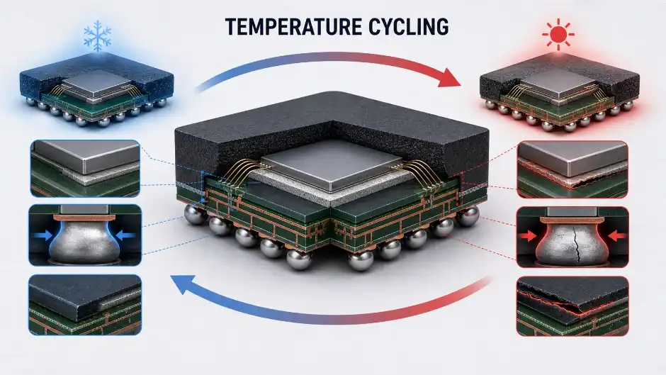
| Failure mechanism | Where it occurs | Useful analysis |
|---|---|---|
| Solder fatigue crack | BGA balls, leads, module joints | Resistance monitoring, X-ray and cross-section |
| Delamination | Mold compound, die attach, substrate interface | Scanning acoustic microscopy and cross-section |
| Wire-bond damage | Bond heel, pad or interface | Electrical test, pull test and microscopy |
| Package or die crack | Silicon, ceramic, molding compound | Optical inspection, acoustic imaging and sectioning |
| Intermittent open | Solder or internal interconnect | In-situ event detection and four-wire resistance measurement |
Temperature Cycling, Thermal Shock and Power Cycling
| Method | How stress is applied | Best use |
|---|---|---|
| Temperature cycling | One chamber changes air temperature through controlled cycles | Package and interconnect fatigue qualification |
| Thermal shock | Specimen transfers rapidly between stabilized hot and cold zones | Abrupt transition and severe thermomechanical stress |
| Power temperature cycling | Ambient cycling plus controlled device energization | Power semiconductor and powered assembly evaluation |
| Power cycling | Junction temperature changes mainly through electrical loading | Die attach, bond wire and power-module lifetime work |
| HAST/PCT | High temperature, humidity and pressure | Moisture-related package mechanisms, not a substitute for cycling |
When transfer time is central, review DERUI’s temperature chamber versus thermal shock chamber comparison. Moisture testing requires different equipment, such as a PCT/HAST chamber.
How to Build a Repeatable Test Program
-
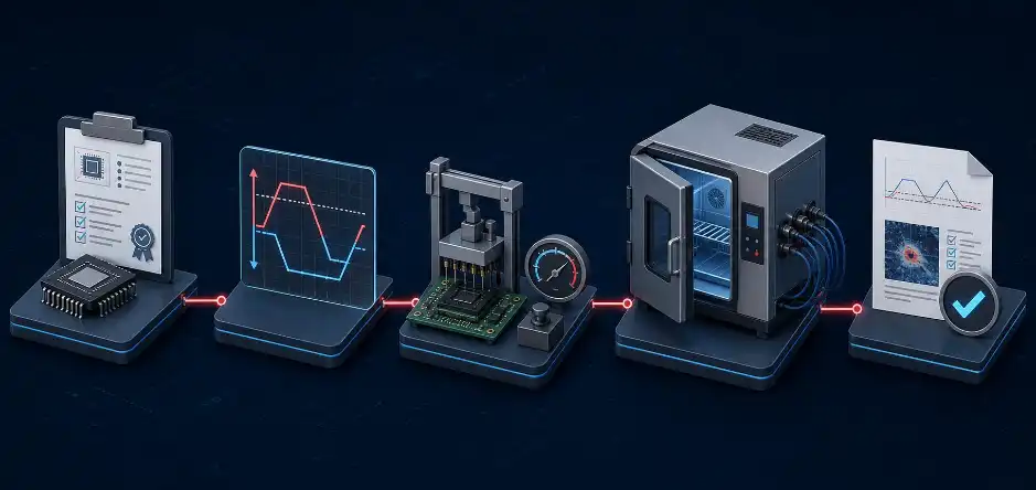
Confirm the governing requirement
Record the exact standard revision, test condition, qualification plan, sample quantity and acceptance criteria.
-
Define specimen configuration
Document package type, board, socket or tray, orientation, loading density, moisture preconditioning and whether parts are powered.
-
Measure product temperature
Attach thermocouples to representative devices and difficult locations. Chamber air is not proof that the package has reached the required dwell condition.
-
Control loading and airflow
Keep fixture and board placement repeatable. Avoid blocking supply and return airflow or mixing greatly different thermal masses without validation.
-
Monitor electrical continuity
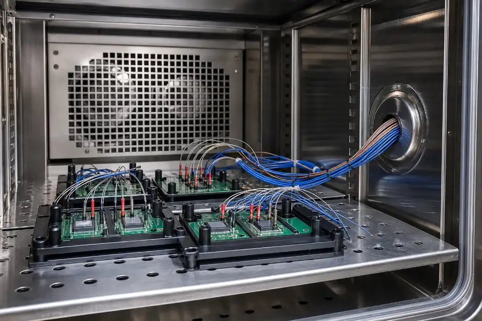
Where required, synchronize resistance or functional events with chamber temperature and device thermocouples to capture transient opens.
-
Close the failure-analysis loop
Define interim reads, final electrical tests, visual inspection, acoustic microscopy, X-ray and destructive analysis before testing begins.
How to Select a Semiconductor Temperature Cycling Chamber
Rate Performance with the Real Load
Empty-chamber ramp rate is not product temperature transition. Provide the supplier with board count, trays, sockets, fixture mass, package density and any powered heat load. Ask for the guaranteed performance across the required range with that load.
Separate Uniformity from Stability
Controller fluctuation at one sensor does not describe spatial temperature variation. Confirm the mapping method, sensor locations, setpoints and allowable loaded-workspace volume.
Plan Feedthroughs and Monitoring
Specify thermocouple channels, resistance measurement leads, power, communication and fixture connections. Ports should be large enough for connectors yet sealed to avoid uncontrolled air leakage.
Design for Long-Duration Cycling
Qualification can involve many cycles. Review compressor duty, defrost strategy, alarm recovery, program restart, data retention, preventive maintenance and remote notification.
For suitable equipment, review DERUI’s rapid temperature change test chamber and temperature shock chamber.
Semiconductor Chamber RFQ Checklist
- Standard revision and test condition
- Low/high setpoints, transition and dwell requirements
- Cycle count and expected annual throughput
- Package, board, socket and tray dimensions
- Total load mass and powered heat dissipation
- Device temperature measurement locations
- Electrical continuity or functional monitoring channels
- Workspace uniformity and calibration requirements
- Ports, connectors and data interfaces
- Alarms, remote access, recovery and documentation
Configure a Semiconductor Reliability Test Chamber
Send DERUI your JEDEC or customer test profile, package loading, fixture mass, monitoring channels and throughput target. We can review whether a rapid thermal cycle, thermal shock, temperature/humidity or custom system best matches the program.
Frequently Asked Questions
What is JESD22-A104?
It is a JEDEC test method widely used for repeated temperature cycling of semiconductor packages. Use the current licensed document and applicable qualification specification for exact conditions.
Is thermal shock the same as temperature cycling?
No. Temperature cycling normally changes one chamber’s air temperature, while thermal shock transfers specimens rapidly between stabilized environments.
Should dwell be based on chamber air or package temperature?
The approved procedure governs, but representative package temperature measurement is essential for proving that loaded specimens reached the intended condition.
Why is empty-chamber ramp rate insufficient?
Boards, fixtures and packages add thermal mass and restrict airflow. The device transition can be much slower than the controller reading.
Can resistance be monitored during cycling?
Yes. Appropriate feedthroughs and data acquisition can detect transient opens that disappear after the specimen returns to ambient.
Is HAST a replacement for temperature cycling?
No. HAST accelerates moisture-related mechanisms; temperature cycling primarily accelerates thermomechanical fatigue.
Is the chamber itself JEDEC certified?
It is more accurate to state the conditions and test methods the chamber is designed to support. Qualification depends on the complete procedure, loading, monitoring and results.
Authoritative Reference
JEDEC Solid State Technology Association — standards and publications portal