Burn-In vs Temperature Cycling vs Thermal Shock
Date: 08/21/2026 Categories: Applications、Electronics & Semiconductors Views: 11230
Burn-In vs Temperature Cycling vs Thermal Shock
Choose the right electronics reliability stress by comparing purpose, transition severity, powered operation and required equipment.
Start With the Product Risk, Not the Chamber Specification
Burn-In vs Temperature Cycling vs Thermal Shock should reproduce the environmental stress and operating state that matter to the product. A maximum temperature alone does not define a useful test. Engineers must identify where the product is installed, whether it is powered, how it rejects heat, which functions must be monitored, and what constitutes a failure.
The applicable references may include JEDEC methods, IEC 60068-2-14, product reliability plan. Always use the purchased standard and the approved customer test plan to determine severities, tolerances, dwell times and acceptance criteria. This guide explains equipment planning; it does not replace the governing document.
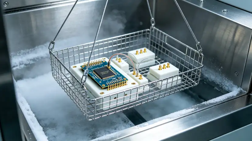
How to Build a Defensible Test Plan
1. Define the use case
Document installation location, duty cycle, expected environment, transport state and credible misuse. Separate storage, non-operating and operating exposures.
2. Choose the governing procedure
Record the exact standard edition, customer specification, sequence, tolerances, preconditioning and recovery requirements.
3. Define functional checks
State what is measured before, during and after exposure. Set objective limits for electrical, optical, communication, safety or mechanical performance.
4. Establish stop conditions
Define specimen overtemperature, smoke or gas alarms, insulation limits, communication loss and chamber faults that require a controlled shutdown.
A minimum test matrix
| Item | What to specify | Why it changes the chamber |
|---|---|---|
| Environmental profile | Setpoints, ramp rates, dwell, cycles and recovery | Determines refrigeration, heating, humidity or pressure capacity |
| Specimen | Dimensions, mass, quantity, material and fixture | Changes workspace, airflow and thermal response |
| Operating state | Powered modes, duty cycle and maximum dissipation | Live heat load can reduce cooling and ramp performance |
| Services | Components, boards or assemblies with fixtures, loads and monitoring appropriate to the selected stress | Determines ports, connectors, isolation and sealing |
| Evidence | Chamber data, product sensors and synchronized functional logs | Allows a failure to be correlated with the actual stress |
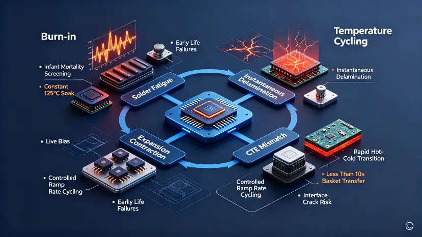
Test Setup and Instrumentation
A representative setup may include Components, boards or assemblies with fixtures, loads and monitoring appropriate to the selected stress. Use production-intent connectors and mounting orientation whenever possible. Keep fixtures light enough to avoid unnecessary thermal lag, but sufficiently rigid to reproduce installation constraints.
Measure the product, not only chamber air
Place product sensors at expected hot and cold locations and near interfaces that may condense or drift. Chamber control data proves the commanded environment; product sensors show the stress that actually reached the device. Synchronize both with functional data so an intermittent event can be traced to a time and condition.
Protect airflow and feedthrough integrity
Leave clearance around the specimen, avoid blocking supply and return air, and seal ports around cables or pipes. Oversized open ports create leakage and local gradients. High-current, high-voltage, optical, RF, coolant or pressure connections require purpose-designed feedthroughs and strain relief.
How to Select the Environmental Chamber
- Confirm the real operating envelope. Specify the required conditions and tolerances, not an unnecessarily extreme catalog range.
- Size the usable workspace. Include fixtures, cable bend radius, access and airflow clearance—not only product volume.
- Calculate live heat load. Give maximum dissipation at the coldest setpoint and during the fastest ramp.
- Define ramp performance correctly. State whether the requirement applies to chamber air or a measurement point on the loaded product.
- List every interface. Fix port diameter, location and quantity before manufacture.
- Match safety to the hazard. Independent limiters, specimen power cutoff, emergency stop, ventilation and remote alarms may be required.
- Request verification evidence. Agree on factory acceptance points, sensor calibration, uniformity checks and supplied reports.
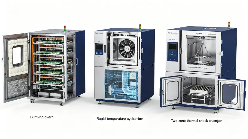
For this application, the usual starting point is a Burn-in oven, cycling chamber or thermal shock chamber. The final configuration must be reviewed against the approved test profile and specimen risk.
Failures the Test Should Help You Diagnose
| Possible observation | Evidence to capture | Useful follow-up |
|---|---|---|
| Early-life defect | Time-aligned functional and chamber log | Repeat at boundary with extra channels |
| Solder fatigue | Product temperatures and electrical trace | Inspect interfaces and cooling path |
| Package cracking | Visual inspection and insulation data | Check sealing, contamination and materials |
| Intermittent operation | Pre/post performance comparison | Confirm whether failure is reversible |
Do not treat a chamber alarm as a product failure or a product interruption as proof of one specific mechanism. Preserve the raw data, photographs, fixture details, software version and exact sequence. Good evidence makes root-cause analysis faster and prevents a pass/fail dispute.
RFQ Information That Prevents an Incorrect Quotation
- Standard, edition, customer specification and complete profile
- Specimen dimensions, mass, quantity and fixture drawing
- Minimum/maximum condition, ramp, dwell and cycle count
- Maximum powered heat dissipation and operating modes
- Cable, fluid, optical, RF, pressure and communication interfaces
- Required sensors, data channels, sampling and remote access
- Known hazards, stop conditions and required safety functions
- Facility power, cooling water, drainage, exhaust, floor loading and access
- Factory acceptance, calibration, installation and training requirements
Configure the Test Around Your Actual Specimen
DERUI can review the profile, specimen drawing, live load, fixture and interfaces before recommending a chamber. This avoids selecting equipment from an empty-chamber temperature range alone.
Frequently Asked Questions
What information is needed before selecting a chamber?
Provide the complete profile, specimen and fixture dimensions, total mass, live heat load, operating state, interfaces, monitoring channels and hazards.
Can the specimen operate during the test?
Yes when the governing procedure and risk assessment allow it. Powered testing requires suitable feedthroughs, load capacity, functional monitoring and an independent shutdown method.
Why is empty-chamber performance insufficient?
The specimen, fixture and live dissipation change airflow, ramp rate and achievable low-temperature performance. Ask for capability under the defined load.
How should chamber and product data be used together?
Synchronize chamber conditions with product temperatures and functional channels. This shows whether an observed event occurred at a meaningful product condition.
Which chamber is normally used for this application?
A Burn-in oven, cycling chamber or thermal shock chamber is a logical starting point, but profile, size, live load, interfaces and safety determine the final configuration.
Does owning the chamber prove compliance?
No. Compliance depends on the complete approved procedure, calibrated instrumentation, specimen setup, tolerances, acceptance criteria and documented results.
References and Related Resources
Authoritative references
DERUI resources