Environmental Testing for 5G Base Stations and Telecom Equipment
Date: 07/30/2026 Categories: Applications、Telecommunications & 5G Views: 5139
Environmental Testing for 5G Base Stations and Telecom Equipment
A practical guide to translating outdoor deployment risks into temperature, humidity, dust, rain, corrosion and powered-performance tests for AAUs, RRUs and supporting telecom hardware.
5G reliability is a system problem, not only a temperature rating
A 5G radio may be rated for a wide ambient range and still fail in service. Solar heating can raise the enclosure temperature above ambient; humidity can condense after a rapid cool-down; dust can reduce heat-sink performance; salt can attack connectors; and a sealed enclosure can trap heat generated by the electronics.
Effective telecom environmental testing therefore connects an external stress to an observable product response. For an active antenna unit (AAU), remote radio unit (RRU/RRH), baseband unit, power supply, optical module, router or switch, that response may include RF power drift, error vector magnitude, throughput, alarm status, current draw, fan speed, internal temperature or thermal throttling.
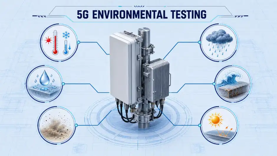
Classify where the equipment will actually operate
Controlled location
Baseband, transport and power equipment may see moderate temperature and humidity, but airflow obstruction, dust accumulation and heat from adjacent racks still matter.
Cabinet or shelter
Equipment is shielded from direct rain and solar radiation but can face broad temperature cycles, condensation, cabinet heat soak and limited ventilation.
Tower, rooftop or pole
AAUs and RRUs can experience solar load, wind-driven rain, dust, salt-laden air, freezing conditions and repeated day/night thermal cycling.
Use standards as a framework, then tailor the profile
The ETSI EN 300 019 series describes environmental classes and tests for telecommunications equipment in different locations. IEC 60068-1 provides the general environmental-testing framework, with the IEC 60068-2 family supplying individual test methods. Ingress protection may be specified using IEC 60529, while customer, operator, regional and product-level requirements can add salt mist, solar radiation, vibration, shock, EMC or radio conformance tests.
| Reference | What it contributes | How to use it |
|---|---|---|
| ETSI EN 300 019 | Telecom-specific environmental classes and test severities by installation location | Select the class matching storage, transport and operating conditions. |
| IEC 60068 | General framework and repeatable climatic/mechanical test methods | Define specimen state, conditioning, recovery, measurements and tolerances. |
| IEC 60529 / IP requirements | Protection against solid-object and water ingress | Match enclosure claims and installation orientation. |
| Operator or customer specification | Network-specific limits, powered checks and acceptance criteria | Resolve conflicts and document the controlling requirement before testing. |
Important: climatic qualification, ingress testing, EMC and RF regulatory conformance are related but separate workstreams. Passing one does not automatically demonstrate compliance with the others.
Choose each test for the failure mechanism it must reveal
| Test | Field risk represented | Useful observations |
|---|---|---|
| High- and low-temperature operation | Seasonal extremes, cold start, enclosure heat soak | Boot success, RF output, alarms, current, internal temperatures and derating |
| Temperature cycling | Day/night cycling and mismatched material expansion | Intermittent connections, solder fatigue, seal movement and calibration drift |
| Damp heat / condensation | Humid climates, rain followed by cooling, cabinet moisture | Insulation resistance, corrosion onset, optical/RF connector stability and leakage |
| Dust ingress | Roadside, desert, industrial and construction exposure | Seal integrity, filter loading, airflow loss and heat-sink temperature rise |
| Rain / water ingress | Wind-driven rain, spray and installation leakage | Ingress paths, drainage, gasket compression and functional interruptions |
| Salt mist | Coastal and marine atmospheres | Connector, coating, fastener and exposed-metal corrosion |
| Solar / UV exposure | Rooftop and pole-mounted solar load | Surface temperature, material ageing, colour change and thermal margin |
| Vibration and shock | Transport, tower motion, handling and installation | Connector retention, structural integrity and intermittent faults |
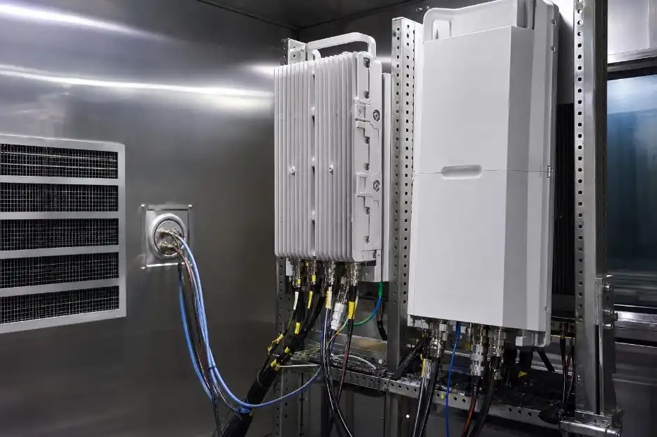
Measure function during exposure, not only before and after
Unpowered conditioning can identify material and enclosure damage, but it may miss thermal throttling, timing problems and intermittent performance loss. When the method permits, power the unit at a representative traffic or RF load and route cables through properly sealed chamber ports.
- Log chamber air, product inlet air and critical internal temperatures.
- Record RF output, EVM or another agreed radio-quality metric.
- Track throughput, packet errors, link status and alarm events.
- Measure voltage, current and total power to identify abnormal loading.
- Capture fan/pump speed and the exact point where derating begins.
- Synchronize all timestamps so an event can be matched to the stress profile.
Match the chamber to specimen size, stress and measurement method
Temperature & humidity chamber
For powered operation, damp heat, cold start and most component or small radio-unit profiles.
Rapid-change chamber
For repeated thermal transitions where ramp rate at the specimen and recovery under heat load matter.
Dust test chamber
For controlled dust concentration, circulation, exposure time and optional specimen operation.
Walk-in chamber
For outdoor cabinets, multiple radios, loaded racks and systems that need realistic spacing and wiring.
Salt spray chamber
For coastal-exposure screening of coatings, fasteners, connectors and exposed metal interfaces.
Integrated monitoring
Ports, insulated cable glands, fixtures, data logging, power interlocks and external RF or network instrumentation.
Do not choose capacity from product dimensions alone. Leave airflow clearance, account for mounting orientation and cable bend radius, and confirm that the loaded chamber—not an empty chamber—can meet the required profile.
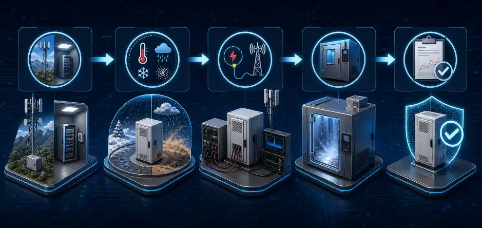
A five-step path from deployment to evidence
Classify
Define location, climate, protection and service life.
Map
Link standards and customer clauses to risks.
Load
Set powered state, RF/network load and heat.
Measure
Define synchronized channels and pass/fail limits.
Verify
Review data, anomalies, recovery and final inspection.
Information that produces an accurate chamber proposal
Product and load
- Unit type and dimensions
- Quantity and mounting orientation
- Powered heat load in watts
- Mass and fixture material
Profile and environment
- Temperature/humidity limits
- Ramp rate and dwell time
- Deployment class and standards
- Dust, water, salt or solar needs
Interfaces and acceptance
- Power, fibre, RF and Ethernet ports
- Measurement channels
- Pass/fail limits and reporting
- Facility voltage, cooling and space
5G telecom environmental testing FAQ
Which standards apply to 5G base station environmental testing?
ETSI EN 300 019 is commonly used to classify telecom installation environments, while IEC 60068 provides general principles and individual environmental test methods. IEC 60529 may support ingress claims. The final plan should also incorporate operator, customer, regional, EMC and radio-conformance requirements.
Should the 5G radio be powered during temperature testing?
Powered testing is valuable when functional drift, thermal derating or alarm behaviour is part of the risk. Confirm that the chosen method allows operation, then define RF/network load, monitoring channels, heat output, cable routing and safety interlocks.
How is chamber size selected for an AAU or outdoor cabinet?
Use the installed specimen envelope plus airflow clearance, fixture volume, cable bends and service access. For powered systems, verify cooling capacity and uniformity at the real heat load. Large cabinets or multiple units may require a walk-in chamber.
Can one chamber perform temperature, humidity, dust and rain tests?
Temperature and humidity are commonly combined, but dust and rain usually require dedicated equipment because their circulation, drainage, contamination control and construction differ. A risk-based test program can sequence results from several chamber types.
What data should be recorded during the test?
Record chamber conditions, product inlet and internal temperatures, RF or network performance, alarms, voltage, current, power, cooling-system behaviour and operator events on synchronized timestamps. This makes deviations reproducible and supports root-cause analysis.
Turn your telecom deployment conditions into a chamber specification
Send DERUI the equipment dimensions, powered heat load, target environmental class, profile and monitoring requirements. Our team can recommend the chamber format, ports, fixtures and control options needed for a repeatable test.