Automotive Electronics Environmental Testing: ISO 16750 Test Methods and Chamber Selection
Date: 07/29/2026 Categories: Applications、Automotive & EV Views: 9479
Automotive & EV Application Guide
Automotive Electronics Environmental Testing: ISO 16750 Test Methods and Chamber Selection
Translate real vehicle conditions into defensible laboratory tests—and specify an environmental chamber around the component, load, monitoring, and test profile that matter.
What Is ISO 16750?
ISO 16750 is an international series for environmental conditions and testing of electrical and electronic equipment installed in road vehicles. The current 2023 editions cover general requirements, electrical loads, mechanical loads, climatic loads, and chemical loads.
The series applies to systems and components according to their mounting location in or on the vehicle. That detail matters: an ECU in the passenger compartment does not experience the same temperature, moisture, vibration, or chemical exposure as a sensor mounted in the engine compartment or near a wheel.
ISO 16750 is not a universal test recipe with one temperature profile for every device. Engineers use the component function, installation location, operating state, vehicle architecture, customer specification, and applicable standard edition to define a test plan. The acceptance criteria also come from the product specification or customer requirements.
Which Automotive Electronics Need Environmental Testing?
Environmental qualification may be required for low-voltage electronics, high-voltage EV systems, sensors, actuators, and assemblies. Typical devices under test include:
- Electronic control units (ECUs) and domain controllers
- Battery management systems (BMS) and battery disconnect units
- On-board chargers, DC-DC converters, and traction inverters
- ADAS cameras, radar modules, lidar units, and ultrasonic sensors
- Power steering, braking, airbag, and chassis control modules
- Infotainment systems, displays, instrument clusters, and telematics units
- Connectors, wiring harnesses, relays, switches, and power distribution units
- LED drivers, exterior lighting modules, and body electronics
- Electric pumps, fans, motors, and electronic actuators
- Charging inlets, vehicle communication controllers, and thermal-management controls
Testing is most useful when it represents the real component state. Depending on the validation objective, the device may be unpowered, powered, communicating over a vehicle bus, driving a representative load, or monitored continuously for intermittent faults.
How the ISO 16750 Series Is Organized
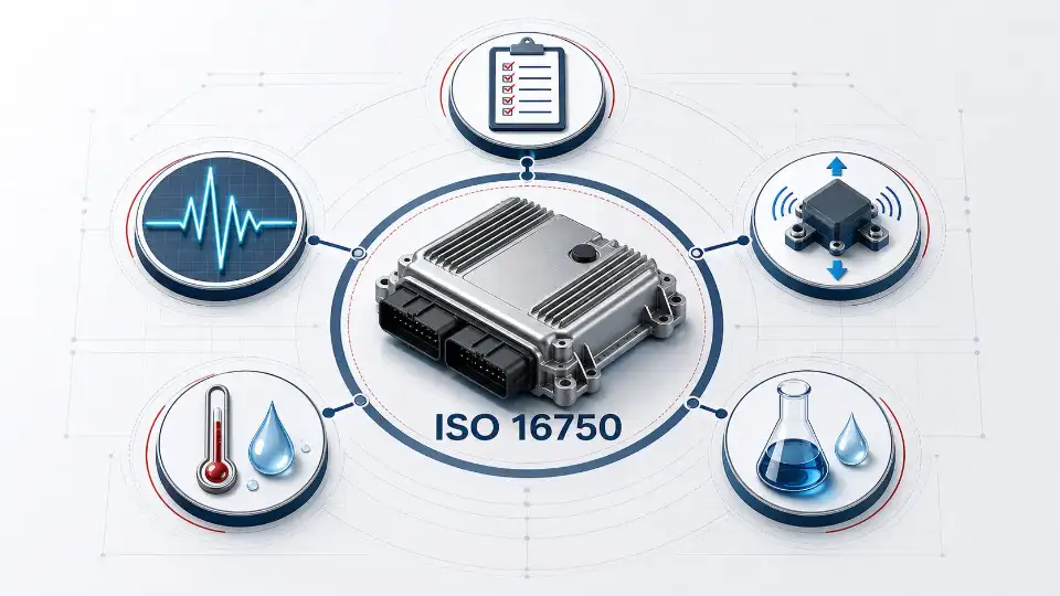 ISO 16750 organizes automotive electronic validation around general, electrical, mechanical, climatic, and chemical considerations.
| Part | Main scope | Typical engineering concern | Typical equipment |
|---|---|---|---|
| ISO 16750-1 | General terminology and requirements | Test tailoring, mounting location, operating modes, functional status | Test plan and measurement system |
| ISO 16750-2 | Electrical loads | Supply variations, transients, interruption, reverse voltage, and related electrical stresses | Programmable power supply, transient generator, electronic load, data acquisition |
| ISO 16750-3 | Mechanical loads | Vibration, mechanical shock, free fall, and mounting-related stress | Electrodynamic or hydraulic shaker, shock equipment, fixtures |
| ISO 16750-4 | Climatic loads | High and low temperature, temperature cycling, humidity, condensation, water, dust, salt mist, and other climatic exposure | Temperature/humidity chamber, rapid-change chamber, thermal shock chamber, dust/rain/salt-spray equipment |
| ISO 16750-5 | Chemical loads | Exposure to automotive fluids and chemicals expected at the mounting location | Chemical exposure setup plus controlled conditioning equipment |
Electromagnetic compatibility is not covered by ISO 16750. EMC validation normally uses separate standards and customer specifications. Likewise, component-level qualification such as AEC-Q100 or AEC-Q200 can complement—but does not automatically replace—validation of the complete automotive electronic assembly in its enclosure and intended operating state.
Key ISO 16750-4 Climatic Tests for Automotive Electronics
For an environmental chamber project, ISO 16750-4 is usually the most relevant part of the series. The required tests and severity depend on where the component is installed and how it operates.
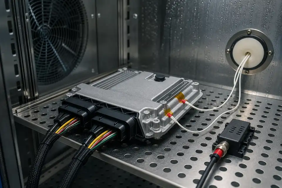 A representative powered ECU setup with product thermocouples, sealed cable routing, and controlled chamber airflow.
High-Temperature Testing
High-temperature exposure checks whether materials, solder joints, seals, sensors, displays, capacitors, and electronic functions remain stable under operating or storage heat. An under-hood controller may require a more severe profile than a cabin-mounted module.
The chamber must be selected for the heat produced by an energized device. A chamber that reaches the target temperature while empty may fail to control it when an inverter, power supply, or loaded ECU releases heat. Tell the chamber manufacturer the maximum specimen heat dissipation, cable losses, fixture mass, and powered operating mode.
Low-Temperature Testing
Low-temperature tests reveal cold-start problems, brittle materials, seal contraction, display response changes, lubricant effects, reduced capacitance, and timing or sensor drift. For powered testing, use insulated feedthroughs and a monitoring system that can capture startup behavior and brief communication faults.
Temperature Step and Temperature Cycling Tests
Temperature cycling repeatedly expands and contracts materials with different coefficients of thermal expansion. It can expose cracked solder joints, connector fretting, delamination, seal leakage, and intermittent electrical connections.
Do not choose a chamber from its headline ramp rate alone. Confirm whether the specified rate is measured in empty-chamber air or at the specimen, whether it applies across the full working range, and how much product mass and heat load the quoted performance allows.
Thermal Shock
Thermal shock creates a much faster transition between hot and cold conditions than conventional temperature cycling. It is useful when the test specification requires abrupt transfer or when the objective is to accelerate thermomechanical stress.
A two-zone or three-zone temperature shock test chamber may be appropriate when transfer time is critical. A single-zone rapid-change chamber is usually more flexible for controlled ramps and powered functional testing. Read the comparison of a temperature test chamber versus a thermal shock chamber before selecting the architecture.
Damp Heat and Humidity Exposure
Humidity can cause corrosion, insulation resistance loss, electrochemical migration, connector oxidation, swelling, and seal failure. Condensation is especially important because liquid water on a powered PCB can reveal vulnerabilities that steady high humidity may not expose.
For humidity testing, specify the actual temperature-humidity operating envelope rather than quoting only the widest advertised ranges. Very low humidity at low temperature may be physically unavailable because of the air dew point. A properly sized temperature and humidity test chamber should provide a documented operating envelope and controlled water quality.
Dust, Water, Salt Mist, and Other Exposure
Exterior modules, wheel-area sensors, connectors, charging components, and underbody electronics may also require ingress or corrosion evaluation. These exposures normally use dedicated equipment rather than a standard climatic chamber. The complete validation plan should consider the sequence of environmental stresses because preconditioning can change sealing performance and failure behavior.
Mounting Location Determines the Test Severity
A useful test plan starts with the mounting location—not with a chamber catalog. The table below illustrates the engineering logic. It does not prescribe test limits.
| Typical location | Dominant stresses | Examples | Chamber implications |
|---|---|---|---|
| Passenger compartment | Moderate temperature, solar heating, humidity, operating cycles | Infotainment, displays, body controllers | Temperature/humidity chamber; powered monitoring ports |
| Engine or powertrain area | High heat, rapid temperature change, vibration, fluids | ECUs, sensors, actuators, power electronics | Wider temperature range, heat-load capacity, rapid cycling |
| Exterior or underbody | Water, dust, salt, freezing, shock, corrosion | ADAS sensors, lighting, connectors | Climatic testing plus dedicated ingress/corrosion equipment |
| EV battery or high-voltage system | Temperature gradients, powered heat load, humidity, high voltage | BMS, inverter, charger, junction box | Electrical isolation, safety interlocks, cable ports, gas/smoke risk assessment where applicable |
How to Build an ISO 16750 Automotive Electronics Test Plan
-
Define the device and installation location
Record the component function, mounting location, enclosure, orientation, nearby heat sources, cooling method, expected vibration, electrical architecture, and exposure to water, dust, salt, or fluids.
-
Identify the applicable documents
Confirm the ISO 16750 edition, OEM specification, Tier 1 requirements, regional rules, product specification, drawings, and component-level qualification requirements. Resolve conflicts before testing begins.
-
Define operating modes
Specify when the device is off, in sleep mode, powered, communicating, driving a load, or performing a diagnostic routine. Include supply voltage, current, software version, bus traffic, loads, and fault-monitoring thresholds.
-
Define functional status and acceptance criteria
State what must be measured during exposure, immediately after exposure, and after recovery. Examples include output accuracy, communication errors, insulation resistance, leakage current, memory integrity, diagnostic trouble codes, visual damage, and sealing performance.
-
Specify preconditioning and test sequence
Environmental tests can interact. Temperature cycling may weaken a seal before water testing; vibration may loosen a connector before humidity exposure. Document the sequence and whether the same sample or separate samples are used.
-
Define instrumentation and traceability
List chamber sensors, product thermocouples, voltage and current measurement, CAN or LIN monitoring, data sampling rate, calibration requirements, photos, and event logs. Intermittent faults can disappear after the specimen returns to room temperature, so in-test monitoring is often essential.
-
Run a dry trial
Before the qualification run, verify fixture clearance, airflow, cable sealing, control stability, condensation management, alarms, data synchronization, and emergency shutdown. A short mapping run can reveal specimen temperature lag or hot spots.
How to Select an Environmental Test Chamber for ISO 16750 Testing
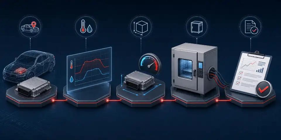 Start with the mounting location and test profile, then account for specimen size, live heat load, chamber configuration, and verifiable results.
1. Select the Chamber Type from the Test Profile
| Test requirement | Recommended chamber type | Best suited to |
|---|---|---|
| Constant high/low temperature and controlled ramps | Temperature test chamber | Storage, operation, endurance, general qualification |
| Combined temperature and humidity | Temperature and humidity chamber | Damp heat, humidity cycles, condensation-related validation |
| Fast controlled temperature ramps | Rapid temperature change test chamber | Accelerated cycling, ESS, powered functional monitoring |
| Abrupt hot-to-cold transfer | Two-zone or three-zone thermal shock chamber | Severe thermomechanical stress and fast transfer requirements |
| Large assemblies, racks, battery systems, or batch testing | Walk-in environmental chamber | High specimen volume and floor-loaded products |
| Temperature/humidity combined with vibration | Integrated chamber with shaker interface | Combined-stress testing using a compatible vibration system |
2. Size the Workspace Correctly
Leave enough clearance around the specimen for stable airflow and sensor placement. The required chamber is determined by product dimensions, fixture, cable bend radius, airflow obstruction, door access, and loading method—not only by the specimen volume. Large or heavy systems may need a reinforced floor, ramp, trolley, or walk-in construction.
3. Account for Live Heat Load
Provide the maximum heat dissipation at every test condition. Include the device under test, electronic loads inside the workspace, lighting, actuators, and power introduced through cables. Ask the supplier to confirm cooling performance at the most demanding low-temperature setpoint and ramp condition.
4. Verify Ramp Rate at the Product
Air temperature can change faster than the specimen core. For a meaningful quotation, provide specimen mass, materials, dimensions, packaging, fixture thermal mass, and required measurement point. Request clarification on whether the guaranteed rate is linear or average and whether it applies with the stated load.
5. Plan Cable Ports and Functional Monitoring
Powered ECU and BMS testing may require high-voltage cables, low-voltage power, CAN/LIN/Ethernet communication, thermocouples, current measurement, pneumatic lines, or coolant connections. Specify the number, diameter, location, sealing method, and electrical isolation of feedthroughs before production.
6. Demand Useful Data, Not Just a Controller Display
The system should support time-stamped temperature and humidity records, alarms, program steps, and exportable test data. When chamber data must align with CAN messages or electrical measurements, define time synchronization and sampling requirements in the RFQ.
7. Evaluate Uniformity, Stability, and Calibration
Temperature fluctuation at the control sensor is not the same as spatial uniformity across the workspace. Ask how performance is measured, at which setpoints, with what load, and under which applicable equipment verification method. Confirm sensor calibration, traceability, calibration access, and the documentation supplied with the chamber.
8. Review Safety Before Adding a Powered Specimen
Risk controls depend on the device. Common requirements include independent over-temperature protection, leakage protection, emergency stop, door interlock, specimen power shutdown, fault outputs, ventilation, and remote alarms. High-voltage or energy-storage components require a project-specific risk assessment; a standard climatic chamber should not be assumed safe for a hazardous battery test.
Common Failures Revealed by Automotive Environmental Testing
| Observed failure | Possible environmental mechanism | Useful diagnostic evidence |
|---|---|---|
| Intermittent communication loss | Connector movement, cracked solder joint, timing drift, condensation | Bus log, supply trace, chamber record, product thermocouple |
| Sensor output drift | Temperature sensitivity, moisture absorption, material stress | Reference sensor comparison before, during, and after exposure |
| Leakage current or insulation loss | Humidity, condensation, ionic contamination, damaged sealing | Insulation measurement, visual inspection, contamination analysis |
| Housing crack or seal leakage | Differential thermal expansion, embrittlement, mechanical stress | Photos, dimensional inspection, leak or ingress test |
| Failure only during cold start | Component tolerance shift, reduced capacitance, startup timing | High-speed voltage/current capture and functional log |
| Overheating under load | Insufficient derating, cooling loss, high ambient temperature | Multi-point product temperature and electrical load record |
Testing Mistakes That Produce Weak or Misleading Results
- Using one generic profile for every component: mounting location and operating state must drive severity.
- Qualifying only an unpowered specimen: intermittent functional failures may remain undetected.
- Choosing by empty-chamber specifications: specimen mass and heat dissipation can change ramp and recovery performance.
- Blocking airflow: crowded shelves and large fixtures create uncontrolled gradients.
- Measuring only chamber air: the product may lag far behind the programmed setpoint.
- Ignoring condensation: uncontrolled dew formation can either invalidate a dry test or omit an intended moisture stress.
- Failing to synchronize data: a chamber log without electrical or bus data makes intermittent failures difficult to diagnose.
- Calling equipment “ISO 16750 certified” without context: conformity belongs to a defined test method and product evaluation, not simply to owning a chamber.
Environmental Chamber RFQ Checklist
Send the following information to obtain an accurate chamber configuration and quotation:
- Applicable standard edition and customer specification
- Required test names and complete profiles
- Minimum and maximum temperature
- Required humidity conditions and condensation requirements
- Ramp rate and the point at which it must be achieved
- Specimen dimensions, weight, material, and quantity per batch
- Fixture dimensions, mass, and airflow obstruction
- Maximum live heat dissipation at each condition
- Powered operating modes and supply requirements
- Number and type of cable, fluid, and communication feedthroughs
- Required sensors, channels, sampling rate, and data interface
- Safety hazards and required interlocks
- Laboratory power, water, drainage, ventilation, and space constraints
- Calibration, documentation, installation, and training requirements
Build the Right Automotive Electronics Test System
DERUI designs environmental test chambers for ECUs, sensors, BMS units, power electronics, connectors, displays, and other automotive components. Available solutions include compact temperature/humidity chambers, rapid temperature change systems, thermal shock chambers, and custom walk-in chambers.
For a useful recommendation, send us your test profile, specimen size and mass, live heat load, mounting fixture, cable requirements, and applicable standard. Our engineers can review the operating envelope and propose a chamber configuration around the actual test—not only the maximum temperature printed on a specification sheet.
Frequently Asked Questions
What does ISO 16750 cover?
ISO 16750 covers environmental conditions and tests for electrical and electronic equipment installed in road vehicles. Its five parts address general requirements, electrical loads, mechanical loads, climatic loads, and chemical loads. EMC is outside its scope.
Which part of ISO 16750 applies to environmental chambers?
ISO 16750-4 addresses climatic loads and is the main reference for temperature, humidity, and related climatic testing. Other parts may require separate electrical, vibration, shock, or chemical-exposure equipment.
Does every automotive ECU use the same ISO 16750 test profile?
No. Test conditions depend on mounting location, component function, operating mode, vehicle architecture, customer requirements, and the applicable edition of the standard. An engine-compartment ECU and a cabin display should not automatically receive the same profile.
What chamber is best for automotive ECU testing?
A temperature and humidity chamber is suitable for many ECU climatic tests. A rapid temperature change chamber may be required for faster controlled cycling, while a thermal shock chamber is appropriate when the procedure specifies abrupt transfer. Workspace, heat load, cable routing, and live monitoring must also be considered.
Can an ECU be powered during temperature and humidity testing?
Yes, when required by the test plan and risk assessment. The setup may include a programmable power supply, representative loads, CAN or LIN monitoring, thermocouples, protected feedthroughs, and an automatic shutdown circuit.
Is ISO 16750 the same as AEC-Q100?
No. ISO 16750 addresses vehicle electrical and electronic systems or components in relation to their environmental conditions and mounting location. AEC-Q100 is a component-level stress-test qualification specification for packaged integrated circuits. A product program may use both.
Is a chamber itself ISO 16750 certified?
It is more accurate to state that a chamber provides conditions or capabilities needed for specified ISO 16750 test methods. Product conformity depends on the complete test procedure, specimen configuration, instrumentation, calibration, acceptance criteria, and results.
What information is needed to size an automotive test chamber?
Provide the specimen and fixture dimensions, total mass, quantity, heat dissipation, temperature and humidity profile, ramp rate, powered operating state, cable ports, safety risks, and data-acquisition requirements.
Authoritative References
Use the official ISO catalog to confirm current editions and obtain the complete standards needed to define test severities and procedures.