PV Module Test Chamber Loading Layout: Panels, Racks and Cable Routes
Date: 11/09/2026 Categories: Resources、Technical articles Views: 7110
The number of photovoltaic modules that fit into a test chamber cannot be calculated from cubic volume alone. Module orientation, the rack, door access, airflow and monitoring connections determine whether a proposed load is practical. Develop a dimensioned loading layout before selecting the chamber size or comparing quotations.
Define the Module as It Will Be Tested
Start with the complete module drawing, including the frame, junction box, leads and connectors. Specify whether the specimen is framed, frameless, rigid or flexible and identify the permitted support points. A panel’s shipping dimensions may not describe its installed test envelope.
List the quantity required for each test batch, the mass of each module and any variation across the product range. If the chamber will test several formats, identify the largest geometry and the most demanding load separately. The heaviest module and the module with the most awkward cable arrangement may not be the same item.
Identify the test programme and edition used by the laboratory. IEC 61215-2 addresses PV module qualification test procedures, but a climate chamber is only part of that programme. Temperature/humidity exposure, electrical measurements and any required light-source equipment must be scoped separately rather than assumed from a standards list.
Select a Rack and Orientation That Can Be Loaded
Compare the assembled rack with the clear door opening, not only with the internal chamber dimensions. Include trolley wheels, handles, guides, restraints and cable protection. Check the complete movement from the preparation area to the final test position.
Vertical loading can provide a convenient arrangement for some full-size modules, but it is not a universal requirement. The selected method, module construction, supports and handling rules determine the appropriate orientation. A flexible module may need support that changes both the occupied area and the airflow path.
| Layout input | What the drawing should show | Why it matters |
|---|---|---|
| Module support | Contact points, restraints and permitted orientation | Avoids unintended loading or blocked surfaces |
| Rack envelope | Maximum width, depth and height with handles and leads | Establishes fit through the door and into the workspace |
| Trolley and floor | Total mass, wheel loads, sill and ramp | Supports the handling and floor assessment |
| Access | Loading direction, removal space and connector reach | Allows safe setup and repeatable operation |
A drawing that shows the rack inside the chamber is incomplete if it does not show how the loaded rack gets there. Review turning areas and any change in floor level before finalizing the room.
Keep Airflow and Measurement Space in the Layout
Do not use every remaining gap for another module. Identify air supply and return locations and keep the load arrangement compatible with the required temperature distribution. Flat modules can behave as barriers when placed across the intended circulation path.
Set spacing through the approved test arrangement and loaded-performance assessment, not a generic percentage of chamber volume. Rack members, support pads and cable bundles can also create local restrictions. Mark these features on the loading drawing so the thermal review considers the actual assembly.
Define where module-temperature sensors will be attached and how they will be identified. Route their leads so they do not snag during movement or interfere with the door seal. Where electrical monitoring is required, distinguish measurement leads from power circuits and specify the feedthrough arrangement.
Any powered or biased operation needs a separate electrical and heat-load review. Do not infer safe powered testing from the chamber’s supply voltage or from the presence of an access port.
Work Through a Geometric Example Before Claiming Capacity
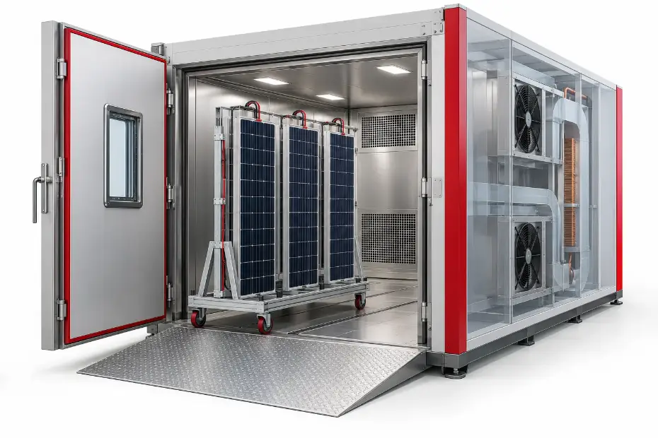
The dimensions below are hypothetical inputs for a layout exercise. They are not a DERUI chamber specification, a recommended clearance or evidence of loaded temperature performance. In this exercise, the modules occupy parallel slots along the rack depth; they are not placed side-by-side across the rack width. The conceptual illustration is not dimensioned to this example.
| Illustrative input | Assumed value | What it establishes |
|---|---|---|
| Each module | 2,000 × 1,000 × 40 mm | Starting module geometry only |
| Module arrangement | Three modules in parallel front-to-back rack slots | Batch objective; spacing still requires review |
| Loaded rack envelope | 1,200 W × 700 D × 2,200 H mm | Assumed complete rack, including protrusions |
| Clear door opening | 1,250 W × 2,300 H mm | A preliminary straight-through geometric check |
The assumed opening is wider and taller than the assumed rack, but that fact alone does not approve the route. Check sill height, wheel movement, alignment, handling tolerance, turns and any cable or handle that extends during loading. Then assess the space around the rack inside the room.
Increasing the batch to four modules requires a new rack and load review. It is not justified by multiplying the first arrangement’s chamber volume by four-thirds. Likewise, passing the geometric check does not establish uniformity, transition time or module stabilization under load.
Turn the Drawing into a Purchase Specification
A useful chamber inquiry joins the loading drawing to the complete environmental sequence. Provide the temperature and humidity points, transitions, dwell conditions, interruption rules and required records. Identify whether the acceptance requirement applies to chamber air, module temperatures or both.
Specify the rack and monitoring supply scope. Ask whether the quotation includes the rack, trolley, restraints, cable feedthroughs, specimen sensors and external measurement interfaces. Name the party responsible for electrical evaluation and any equipment outside the chamber.
The walk-in solar panel test chamber page covers the equipment configuration. For the surrounding facility, review walk-in chamber options and submit the site route, door constraints, floor loads and utilities with the loading layout.
Accept the Agreed Arrangement, Not an Empty Room Alone
Before acceptance, identify the loading arrangement that the demonstration will represent. Record module or representative-load identity, rack position, sensor locations and the operating sequence. A different rack, greater powered heat or additional modules can change the performance question.
Check practical handling as well as environmental records. Verify that the agreed trolley enters, the door closes correctly, connectors remain accessible and cables do not cross seals or obstruct circulation. Agree how interruptions and deviations will be recorded.
Use the FAT acceptance record to organize evidence, keeping chamber acceptance separate from module qualification. A chamber demonstration does not certify the PV module or replace the laboratory’s complete qualification programme.
Create a Loading Drawing That Another Operator Can Repeat
A repeatable PV loading drawing identifies more than the outline of a rack. Number the module positions, show the frame contact points and mark the cable and temperature-sensor paths. Include the direction of entry and any removable handle or restraint used during loading.
Record which surfaces must remain exposed and how the arrangement relates to chamber circulation. Keep sensor access available after all modules are installed. A probe location that can only be reached before the last module is loaded may be impractical for routine setup or inspection.
Use a revision identifier for the module and rack combination. A replacement module with a different junction box, lead length or frame depth can alter the working envelope even if its nominal area is similar. The drawing should let another operator recognise that change before beginning a qualification sequence.
Compare Batch Capacity with Test Throughput
A larger nominal batch is not automatically a more productive laboratory. Consider loading time, fixture preparation, sensor connection, test duration and the consequences of an interrupted run. These factors can be evaluated without promising a particular annual throughput.
For two proposed arrangements, compare the same module format and procedure. Identify whether the higher capacity requires another rack, different loading equipment or longer preparation. Ask whether the stated batch has been geometrically reviewed only or also represented in the agreed environmental demonstration.
Where the laboratory handles several module families, list the largest footprint and the most demanding thermal or electrical arrangement separately. One model need not govern every selection parameter. This prevents an equipment decision based on the single panel that happened to be available during the first quotation.
Agree the Supply Boundary for Racks and Measurements
List who supplies the module rack, trolley, restraints, specimen sensors and external electrical instruments. Record which drawings need approval before manufacture and which items arrive separately at the destination laboratory.
Distinguish environmental exposure from the complete PV qualification programme. A chamber order can include feedthroughs and monitoring interfaces without including every electrical measurement or light-source function required by the laboratory's procedure.
For acceptance, connect each delivered item to its intended check: handling and door fit, fixture identification, channel continuity or environmental records. A dimensioned loading layout with named responsibilities gives purchasing a better comparison than an unqualified statement that a room holds a certain number of panels.
Questions Before You Specify the Equipment
How many solar panels fit into a walk-in test chamber?
The answer depends on panel dimensions, rack geometry, spacing, door access, mass, cables and the required loaded performance. Internal volume alone is insufficient.
Can modules always be tested vertically?
Use the orientation and supports allowed by the module construction and adopted test method. Review handling, contact points, airflow and monitoring with the proposed rack.
Does a climate chamber also provide sunlight or IV measurement?
Not automatically. Light-source equipment, irradiance control and electrical performance measurements are separate functions that need their own defined supply scope.
Can I increase capacity by reducing gaps between panels?
Only after reviewing the allowed arrangement, airflow, measurement access and loaded performance. A smaller gap can change the test conditions rather than simply add capacity.
Review My PV Module Loading Layout
Send module drawings, batch quantity, rack concept, test programme and monitoring requirements. Ask DERUI to review loading geometry, chamber configuration and site access together.