Thermal Shock Testing for Electronics: Standards, Methods, and Chamber Selection Guide
Date: 05/15/2026 Categories: News、Technical articles Views: 3919
thermal shock testing equipment Testing for Electronics: Standards, Methods, and Chamber Selection Guide
Published: May 2026 | Author: Derui Environmental | Category: Technical Articles | Reading Time: 12 minutes
Thermal shock testing is one of the most demanding forms of environmental stress testing for electronic components, semiconductor devices, automotive parts, and aerospace assemblies. Unlike gradual precision temperature test chambers, thermal shock exposes materials to sudden, extreme temperature transitions that expose structural weaknesses invisible under normal operating conditions.
This guide covers the fundamentals of thermal shock testing, the key international standards that govern it, how to select the right test chamber, and practical guidance for integrating thermal shock testing into your product validation workflow.
If you are new to environmental testing, read our 2026 Environmental Test Chamber Buying Guide for a comprehensive overview of chamber types and selection criteria.
What is Thermal Shock Testing?
Thermal shock testing simulates the rapid temperature transitions that electronic components experience during:
- Power on/off cycles — devices heating from ambient to operating temperature in seconds
- Field environment changes — components moving between outdoor cold and heated interiors
- Aerospace altitude test chambers transitions — avionics experiencing rapid decompression and temperature drops
- Automotive under-hood conditions — engine electronics facing -40°C cold starts to +150°C operating temperatures
The critical difference between thermal shock and standard temperature cycling is rate of change. Standard cycling ramps temperature gradually (typically 1-5°C per minute), while thermal shock transitions can reach 10°C per second or faster, creating mechanical stress that gradual testing cannot replicate.
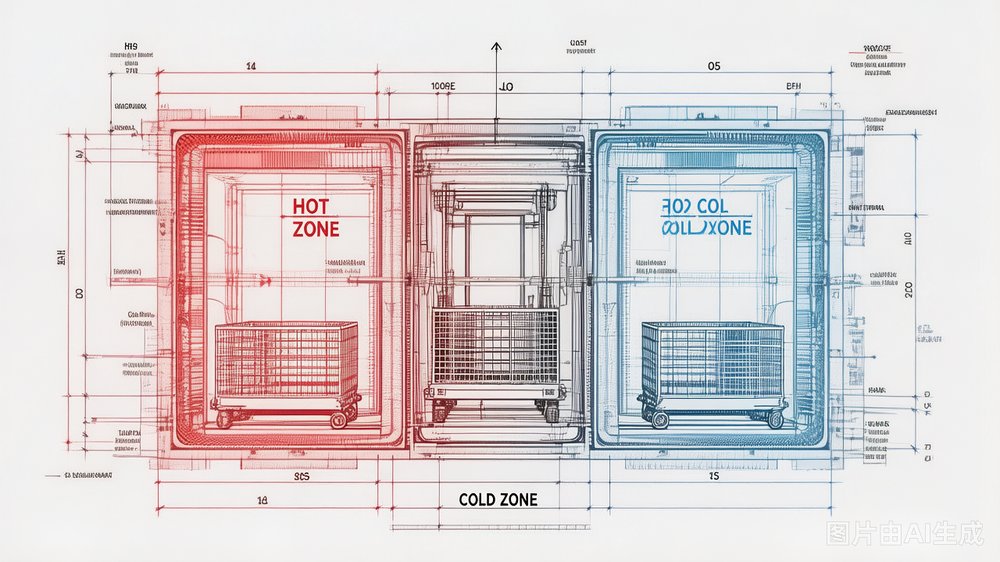
Figure 1: A two-zone thermal shock chamber separates hot and cold compartments, with a mechanical basket that transfers test specimens between zones to achieve the fastest possible temperature transitions.
Types of Thermal Shock Chambers
Two-Zone Thermal Shock Chamber
The most common configuration uses two temperature-controlled zones — a hot chamber (typically +150°C to +200°C) and a cold chamber (typically -40°C to -65°C). A mechanical basket or lift system transfers specimens between zones through a central opening.
Key characteristics:
- Transition time: 5-30 seconds (recovery to 95% of target)
- Temperature range: -65°C to +200°C (standard models)
- Throughput: Higher than three-zone systems
- Best for: Automotive electronics, consumer devices, PCB assemblies
View our full range of Two-Zone Thermal Shock Test Chambers for capacity options from 90L to 500L.
Three-Zone Thermal Shock Chamber
Three-zone systems add an ambient or intermediate temperature zone between hot and cold chambers. This allows testing programs that require a "recovery" period at room temperature between extreme transitions, simulating real-world scenarios more accurately.
Key characteristics:
- Three temperature setpoints: cold / ambient / hot
- Transition profiles: hot-to-cold, cold-to-hot, hot-to-ambient, cold-to-ambient
- Lower mechanical stress per cycle (recovery built in)
- Best for: Aerospace components, semiconductor devices, medical electronics
Liquid-to-Liquid Thermal Shock
For the most aggressive thermal stress, liquid-to-liquid systems immerse specimens directly in hot and cold liquid baths (typically silicone oil or glycol). Transition times can reach under 3 seconds, simulating the harshest conditions.
Best for: Military/aerospace Grade 1 components, precision optical assemblies, sealed packages
Key Standards for Thermal Shock Testing
Thermal shock testing is governed by several international standards, each with specific requirements for temperature ranges, transition rates, dwell times, and cycle counts.
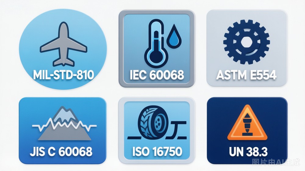
Figure 2: Key international thermal shock testing standards — MIL-STD-810, IEC 60068, ASTM E554, JIS C 60068, ISO 16750, and UN 38.3.
| Standard | Industry | Key Requirements | ||
|---|---|---|---|---|
| MIL-STD-810 | Military/Aerospace | Method 503.7 — temperature shock testing; specifies transition rates and cycle counts per mission profile | ||
| IEC 60068-2-14 | General Electronics | Basic thermal shock test Na (air-to-air) and Nb (air-to-liquid); most widely referenced standard globally | ||
| ASTM E554 | American Standards | Thermal shock testing for valve and fitting materials; references thermal stress resistance | ||
| JIS C 60068-2-14 | Japanese Market | Identical to IEC 60068-2-14 for JIS compliance; essential for Japanese OEM suppliers | ||
| ISO 16750-4 | Automotive | Road vehicles — environmental conditions and testing for electrical equipment; specifies thermal shock for engine compartment components | ||
| UN 38.3 | Battery Transport | Lithium battery transport testing; thermal shock at 72°C to -40°C for cell qualification |
For a complete comparison of thermal shock chamber manufacturers and their standards compliance, see our Environmental Test Chamber Manufacturer Comparison 2026.
Critical Specifications to Evaluate
When selecting a thermal shock test chamber, these specifications determine whether the chamber meets your testing requirements:
Temperature Range
| Application | Minimum Cold Side | Minimum Hot Side | ||
|---|---|---|---|---|
| Consumer electronics | -40°C | +85°C | ||
| Automotive (under-hood) | -40°C | +150°C | ||
| Aerospace | -65°C | +200°C | ||
| Military | -65°C | +200°C |
Transition Time (Recovery Time)
This is the most critical performance metric. Recovery time is measured as the time for the test specimen to reach 95% of the target temperature after zone transfer.
- Fast systems: < 5 seconds (premium chambers, liquid-to-liquid)
- Standard systems: 5-15 seconds (most two-zone air chambers)
- Economy systems: 15-30 seconds (basic models)
For battery thermal runaway testing per UN 38.3, you need recovery times under 7 seconds. Learn more about EV Battery Testing Chambers and their specific requirements.
Temperature Uniformity
Specimens should experience consistent conditions regardless of their position in the chamber:
- ±2°C — Standard requirement for most commercial testing
- ±1°C — Required for aerospace and semiconductor testing
- ±0.5°C — Precision research applications
Chamber Capacity
Choose a chamber with at least 30% more volume than your largest test specimen. Common sizes:
- 90-120L — PCB boards, small electronic modules
- 270-480L — Automotive control units, battery packs
- 680L+ — Full assemblies, server racks
- Walk-in rooms — Large-scale aerospace testing
Applications by Industry
Automotive Electronics
Modern vehicles place extreme demands on electronic control units (ECUs), sensors, and battery management systems (BMS). Thermal shock testing verifies that these components survive the thermal stress of:
- Cold climate starts (-40°C engine start in arctic conditions)
- Under-hood operating temperatures (+150°C near turbochargers)
- Cabin temperature swings (parked in sun, then air-conditioned)
The ISO 16750-4 standard defines the specific test profiles automotive OEMs require. For battery management systems in electric vehicles, UN 38.3 thermal shock cycling is mandatory for transport certification.
Semiconductor and PCB Assemblies
Solder joint integrity is highly sensitive to thermal stress. Thermal shock testing identifies:
- BGA (Ball Grid Array) joint cracks — failure under rapid thermal expansion
- QFN (Quad Flat No-lead) solder voiding issues
- Via-in-pad reliability in high-density interconnects
IEC 60068-2-14 defines the standard thermal shock profiles used by semiconductor manufacturers worldwide.
Aerospace and Avionics
Aircraft electronics face unique challenges: rapid altitude changes cause cabin pressure and temperature to fluctuate dramatically. MIL-STD-810H Method 503.7 defines the thermal shock profiles for military avionics testing, with transition rates and dwell times derived from actual mission flight profiles.
Aerospace testing typically requires three-zone chambers to simulate the complete flight envelope: ground (ambient), altitude (cold + low pressure), and cruise (hot).
Thermal Shock vs. Thermal Cycling: What's the Difference?
Understanding the distinction between these two testing methods is essential for selecting the right approach for your products.
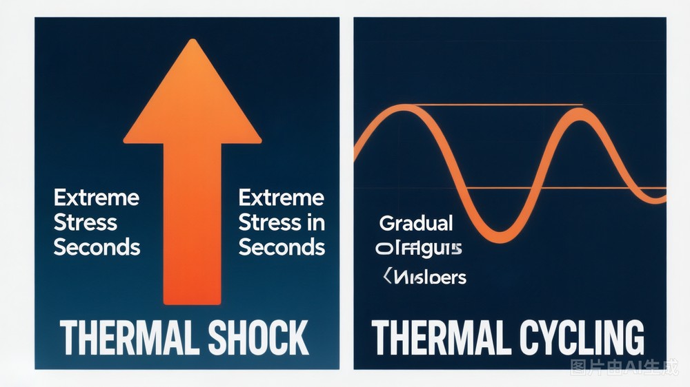
Figure 3: Thermal shock creates rapid temperature transitions (extreme stress in seconds), while thermal cycling uses gradual ramps (cumulative fatigue over hundreds of hours).
| Factor | Thermal Shock | Thermal Cycling | ||
|---|---|---|---|---|
| Temperature change rate | 5-15°C/second | 1-5°C/minute | ||
| Failure mechanism | Extreme mechanical stress, crack initiation | Cumulative fatigue, metal migration | ||
| Test duration | 100-1,000 cycles (days to weeks) | 500-3,000 cycles (weeks to months) | ||
| Equipment cost | Higher (two or three-zone chambers) | Lower (standard temperature chambers) | ||
| Standards | MIL-STD-810, IEC 60068-2-14, UN 38.3 | IEC 60068-2-1, IEC 60068-2-2 | ||
| Best simulates | Power on/off, altitude changes, field use | Long-term reliability, seasonal variations |
Most comprehensive reliability programs include both thermal shock and thermal cycling. Use thermal shock to identify critical design weaknesses, then thermal cycling to evaluate long-term durability.
How to Choose the Right Thermal Shock Chamber
Follow these five steps to select a thermal shock chamber that matches your testing requirements:
Step 1: Define Your Temperature Range
Identify the minimum and maximum temperatures your products will experience. Add a 10-15°C safety margin on each side. For example, if your automotive ECU specification requires -40°C to +150°C, select a chamber rated to at least -55°C to +165°C.
Step 2: Determine Required Transition Time
Match the chamber recovery time to your standard requirements:
- UN 38.3 battery testing → recovery time ≤ 7 seconds
- MIL-STD-810H Method 503 → recovery time ≤ 10 seconds
- General IEC 60068-2-14 Na → recovery time ≤ 30 seconds acceptable
Step 3: Calculate Required Chamber Volume
Measure your largest test specimen in all three dimensions. Add 30% clearance on all sides for airflow. Select the next standard chamber size up from this calculation.
Step 4: Verify Standards Compliance
Confirm the chamber manufacturer can provide:
- Calibration certificates traceable to national standards (NIST, NIM)
- Documentation showing compliance with your target standard
- Chamber validation reports for your specific temperature range
For a detailed comparison of leading manufacturers including Derui, Weiss Technik, Angelantoni, and Sanwood, see our 2026 Environmental Test Chamber Manufacturer Comparison.
Step 5: Evaluate Total Cost of Ownership
The purchase price is only the beginning. Consider:
- Compressor and heating element replacement — typically every 3-5 years
- Calibration costs — annual calibration required by most standards
- Energy consumption — premium chambers use inverter compressors for 30-40% energy savings
- Spare parts availability — local stock vs. import lead times
Common Thermal Shock Testing Mistakes to Avoid
Running Only Thermal Shock Tests
Thermal shock and thermal cycling complement each other. Relying solely on thermal shock can miss fatigue-related failures that only appear under extended cyclic loading.
Ignoring Temperature Uniformity Specifications
If your specification requires ±2°C uniformity but the chamber only delivers ±5°C, your test results may not be valid. Always verify the chamber's specified uniformity at the test temperature setpoints, not just at room temperature.
Selecting an Under-Sized Chamber
Testing specimens that are too large for the chamber causes:
- Inadequate airflow around specimens
- Temperature gradients across the test load
- Invalid test results
Skipping Chamber Validation
Before running qualification tests, validate the chamber's performance using a calibrated thermal data logger placed at the hottest and coldest points of the test load. This establishes the correlation between chamber setpoints and actual specimen temperatures.
Conclusion
Thermal shock testing is an indispensable tool for validating the reliability of electronic components, automotive assemblies, and aerospace equipment. The rapid temperature transitions created in a properly selected thermal shock chamber reveal failure modes that no other environmental test can replicate.
Key takeaways from this guide:
- Transition time is the primary performance metric — match it to your standard requirements
- Two-zone chambers cover most automotive and consumer electronics applications
- Three-zone chambers are essential for aerospace and applications requiring ambient recovery
- Always validate your chamber's actual temperature performance with calibrated instruments
- Combine thermal shock with thermal cycling for a comprehensive reliability program
For guidance on specific applications or to discuss your testing requirements, contact the Derui engineering team. We offer thermal shock chambers ranging from 90L laboratory units to 10,000L walk-in systems, all pre-configured for MIL-STD-810, IEC 60068-2-14, ISO 16750-4, and UN 38.3 compliance.
Related Articles:
- Battery Testing Environmental Chambers: Complete Guide for EV and Energy Storage 2026
- Environmental Test Chamber Manufacturer Comparison 2026: 20 Brands Evaluated
- 2026 Environmental Test Chamber Buying Guide
📘 Extended Reading
If your QC program also includes UV resistance and accelerated weathering (ASTM G154 / ISO 4892-3), read the related guide:
UV Weathering Testing: ASTM G154 & ISO 4892 Guide — covers QUV vs xenon arc chamber selection, lamp types (UVA-340 / UVB-313 / UVA-351), and test cycle parameters used in automotive, coatings, and plastics labs.