Calle Shugang 1, No. 3, Town de Hongmei, Ciudad de Dongguan, Provincia de Guangdong, China

Fabricante de cámaras de prueba ambiental con 20 años de experienciaMás de 3000 entregas a clientes en todo el mundo           Correo electrónico: shirley@deruitest.com
WhatsApp Consultation:+86 135 2795 8363

Banco de pruebas de vibración electromagnética con rango de frecuencia de 600Hz

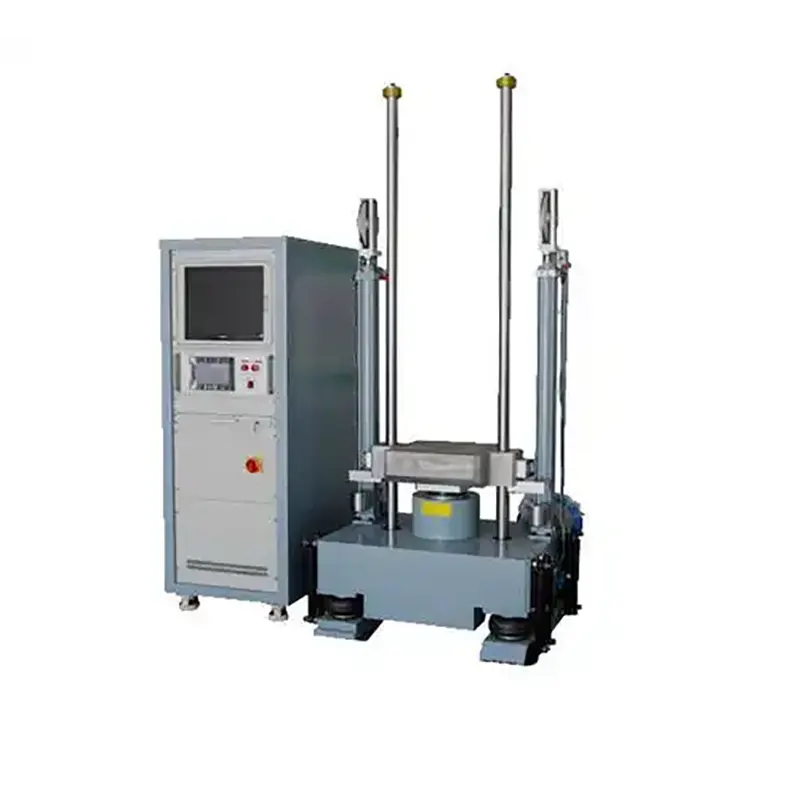
La DERUI DR-D701 electromagnetic vibration test bench should be selected against the specimen's actual sine, random or battery-transport vibration profile. Confirm its drive architecture and loaded force–stroke–velocity–frequency envelope before committing to a test method.

Modelo DR-D701
Engineering Focus Reproduce the specified profile with specimen and fixture installed
Architecture Shaker versus four-point platform requires approved drawing
Frequency Current page conflicts: 600 Hz heading versus 5–5,000 Hz body
Sizing Check total moving mass, force, stroke, velocity, acceleration and axes together
Before Quotation Send profile, load/fixture drawing and FAT targets; request signed DR-D701 datasheet
Segura y confiable
bien hecha
Garantía de calidad
personalización
MensajeWhatsApp
Número de línea directa 15580327593
  • Detalles del producto
  • Preguntas frecuentes
  • Parámetros técnicos
  • Contáctanos
VIBRATION PROFILE → MACHINE ARCHITECTURE → WITNESSED PROOF

Can DR-D701 Reproduce Your Vibration Profile with the Real Payload?

A frequency number alone cannot answer that. The proposed machine must sustain the specified acceleration or displacement after the specimen and fixture are installed, in the required axis, for the full test duration. Use this page to define that engineering decision before ordering DR-D701.

Model evidence status: DERUI's live page identifies DR-D701 but labels it “600Hz” in the H1 while its body claims “5–5,000Hz.” Those cannot both be treated as a single confirmed rating. Ask for the serial/model-specific datasheet.
Start withMethod + waveform + axis
Then sizeSpecimen + fixture + moving element
Then verifyForce + stroke + velocity + control
01 · Identify the machine

Is DR-D701 a Shaker System or a Multi-Point Vibration Platform?

The present page uses “electromagnetic shaker,” “four-point excitation” and “uniform table vibration” as if they describe one unambiguous machine. They may imply different actuator and control architectures. This must be resolved before a technical claim—or a vibration-standard comparison—is credible.

Electrodynamic shaker route

Request the shaker model, armature diameter/mass, amplifier rating, cooling method, controller, head expander or slip table, and loaded performance envelope. A single shaker system is normally selected around force, displacement, velocity and acceleration limits.

Multi-point platform route

Request actuator count/location, table size, payload distribution, phase synchronization, control-point placement and measured spatial uniformity. A “four-point” statement cannot substitute for this evidence.

Publishing gate: obtain a real DR-D701 machine photo, nameplate and mechanical drawing before describing its drive mechanism. The present gallery and prose alone do not resolve the architecture.
02 · Size the load

Why 100 kg and 50 g Cannot Be Quoted in Isolation

The first screening calculation for a shaker is required force ≈ total moving mass × target acceleration. “Total” includes the specimen, fixture, armature or slip-table moving parts, adapters, cables and relevant attachments—not just the specimen on the bench. Resonance and control strategy can increase the practical demand, so final selection requires the vendor's rated envelope and a witnessed run.

Illustrative sizing only—not a DR-D701 capability claim

If a proposed test has a 20 kg specimen, 10 kg fixture and 8 g peak acceleration, even the specimen plus fixture alone call for approximately (20 + 10) × 8 × 9.81 = 2,354 N peak. The moving-element mass, margins and dynamic effects would increase the required system rating. This example cannot prove DR-D701 can perform the test.

Low frequencies: stroke

Large displacement may be required before a high acceleration value is reached. Confirm peak-to-peak stroke and mechanical clearance.

Middle band: velocity

The velocity limit can constrain the sweep even when force and stroke appear adequate.

High frequencies: force/control

Moving mass, fixture resonances and sensor placement govern whether target acceleration is actually maintained.

For a sinusoidal point, peak displacement is x = a/(2πf)². This relationship explains why the same acceleration target can demand very different travel at different frequencies. It is a physics check, not a substitute for the machine's measured performance curve.

03 · Choose the right test

Three Profiles That Should Not Be Merged into One Claim

Buyer request Required input What DR-D701 must demonstrate
IEC 60068-2-6 sinusoidal vibration Frequency band, sweep rate, amplitude/acceleration, axes, duration, functional checks and mounting Loaded sine sweep with control tolerance and resonance handling
IEC 60068-2-64 broadband random vibration PSD breakpoints, overall grms, duration, axes, control/abort channels Installed random controller, force rating, control spectra and data report
UN 38.3 T.3 battery transport vibration Adopted manual revision, specimen definition, mounting orientations, prescribed sweep and post-test criteria Method-specific profile, fixture/monitoring and witnessed evidence; no automatic product certification

IEC describes cURL Too many subrequests by single Worker invocation. To configure this limit, refer to https://developers.cloudflare.com/workers/wrangler/configuration/#limits as a sinusoidal method and IEC 60068-2-64 as broadband random. The UN Manual of Tests and Criteria has a separate T.3 transport-vibration procedure. The final test plan, not the standard name in a brochure, determines suitability.

04 · Control the specimen

The Fixture and Accelerometer Can Decide the Result

Mounting review

Document the bolt pattern, fixture material, stiffness, first fixture resonance, specimen center of gravity and cable routing. A heavy, flexible fixture may consume force and distort the input before the specimen sees the intended vibration.

When the test changes axis, define whether a horizontal slip table or a separate mounting orientation is used. The horizontal assembly's mass and travel must be included in sizing.

Control review

Place control and monitoring accelerometers according to the method and fixture dynamics. Agree single- or multi-point control, abort limits, notching where appropriate, sensor calibration and what waveform/PSD report will be delivered.

At resonances, the specimen can experience an amplified response while the control point remains within tolerance. Compare both control and response channels during FAT.

Battery-specific boundary: the shaker is only one part of a battery test. State the cell/battery condition, voltage and temperature monitoring, containment/exhaust review and post-test inspection separately.
05 · Evidence that closes the purchase risk

Ask DERUI to Prove One Representative Loaded Profile

1. Identify the build

DR-D701 nameplate, actual machine and fixture photos, shaker/actuator, amplifier, controller and axis hardware.

2. Show the envelope

Rated sine/random force, frequency, stroke, velocity, acceleration, payload and table size—with definitions and simultaneous-limit conditions.

3. Witness the profile

Run a representative specimen/fixture mass at agreed low-, mid- and high-band points. Supply raw control data and deviation/abort record.

Also agree factory utilities: electrical input, cooling airflow, floor loading, room noise, lifting/access clearance and any climate-chamber interface. If combined temperature/vibration is required, review the separate combined system rather than assuming it is part of DR-D701.

06 · Buyer questions

Questions to Resolve Before Quotation

Is the DR-D701 frequency ceiling 600 Hz or 5,000 Hz?

The live page states both. The correct value—and whether it changes by configuration—requires a signed DR-D701 datasheet and loaded performance curve. The H1 should not retain “600Hz” until resolved.

Does “100 kg load” mean it can deliver 50 g with 100 kg installed?

No such combined capability is proven by the page. Total moving mass and the force, velocity, stroke and frequency limits must be checked at the required test points.

Is random vibration standard?

The current copy claims sine and random, but the exact controller, amplifier and loaded random-force rating are not identified. Confirm the ordered software and witnessed PSD run.

Does the machine provide four-point excitation?

The phrase appears in the existing copy without a machine drawing. Confirm the actual actuator architecture before making it a product feature.

Will this automatically satisfy UN 38.3?

No. A qualified laboratory must follow the adopted T.3 procedure with the correct specimen and records; the equipment must first be shown capable of the required loaded profile.

Send One Profile. Get a Verifiable System Proposal.

Share the test method and your specimen/fixture data. Ask for the exact DR-D701 configuration, a sizing calculation and a witnessed sample run—not a collection of unrelated headline maximums.

Request DR-D701 engineering review

Attach these four items

  • Waveform or PSD and duration
  • Specimen and fixture mass/drawing
  • Axes and sensor locations
  • Acceptance/reporting requirements
FacebookLinkedInXRedditWhatsApp
  1. P: ¿Para qué se utiliza un banco de prueba de vibración electromagnética?
    A: Un banco de prueba de vibración electromagnética (o shaker) se utiliza para simular entornos de vibración del mundo real en un entorno de laboratorio controlado. Es esencial para probar la durabilidad, fiabilidad e integridad estructural de productos como componentes automotrices, piezas aeroespaciales, electrónica (PCBs) y baterías para garantizar que puedan soportar vibraciones durante el transporte y el uso.

  2. P: ¿Cómo funciona un banco de prueba de vibración electromagnética?
    A: Funciona según el principio del electromagnetismo. Se envía una señal eléctrica (onda sinusoidal, aleatoria o perfil de choque) a un amplificador de potencia, que impulsa una corriente grande a través de una bobina (armadura) suspendida en un campo magnético. Esto crea una fuerza (fuerza de Lorentz) que mueve la bobina y la mesa/plataforma de prueba adjunta, produciendo vibraciones mecánicas precisas y repetibles.

  3. P: ¿Cuáles son las principales ventajas de un shaker electromagnético sobre otros tipos?
    A: Los shakers electrodinámicos ofrecen un control superior en un amplio rango de frecuencias (generalmente de 5 Hz a más de 5.000 Hz), alta capacidad de aceleración (hasta 50 g o más) y la capacidad de replicar con precisión perfiles de vibración complejos como seno, aleatorio y choque. Son generalmente más limpios, precisos y requieren menos mantenimiento que los shakers hidráulicos para la mayoría de las aplicaciones de alta frecuencia.

  4. P: ¿Qué significa “excitación en cuatro puntos” en un banco de prueba de vibración?
    A: La excitación en cuatro puntos se refiere a un sistema de accionamiento donde cuatro actuadores electromagnéticos (uno en cada esquina de la mesa) trabajan en conjunto. Este diseño garantiza una distribución uniforme de la vibración en toda la superficie de prueba, eliminando “puntos calientes” y proporcionando estrés consistente y fiable a todas las muestras de prueba, lo cual es fundamental para resultados precisos y repetibles.

  5. P: ¿Qué industrias utilizan comúnmente sistemas de prueba de vibración electromagnética?
    A: Las industrias clave incluyen Automoción (prueba de componentes y cumplimiento de baterías UN38.3), Aeroespacial y Defensa (calificación de piezas para vibración en vuelo), Electrónica de Consumo (pruebas de durabilidad para teléfonos, portátiles), Fabricación Industrial, y Investigación y Desarrollo laboratorios en diversos sectores.

  6. P: ¿Qué debo buscar al elegir un banco de prueba de vibración electromagnética?
    A: Las especificaciones clave a considerar son: Rango de Frecuencia, Aceleración máxima (g), Desplazamiento (mm), Capacidad de carga (kg), si necesita orientación Vertical u Horizontal y Cumplimiento con Normas (por ejemplo, IEC 60068, MIL-STD). Además, evalúe características como circuitos anti-interferencia, software de control y el soporte y garantía del fabricante.

  7. P: ¿Cómo garantiza la precisión de una prueba de vibración electromagnética?
    A: La precisión se garantiza mediante calibración regular el uso de acelerómetros de referencia, controladores digitales avanzados que gestionan con precisión la señal de entrada, y circuitos integrados antirruido para minimizar el ruido eléctrico. Características como la excitación uniforme en cuatro puntos también previenen sesgos en los datos causados por un movimiento desigual de la mesa.

  8. P: ¿Puede una bancada de vibración electromagnética realizar pruebas multieje?
    A: Un excitador vertical estándar prueba en un eje. Para pruebas multieje, a menudo se utilizan sistemas con una mesa deslizante (para movimiento horizontal) o configurados en un sistema de múltiples excitadores. Algunos sistemas integrados avanzados están diseñados específicamente para la simulación de vibraciones multieje simultáneas.

  9. P: ¿Qué importancia tiene el diseño antirruido en un excitador de vibraciones?
    A: Es sumamente importante. El ruido eléctrico de la fuente de alimentación o del equipo circundante puede contaminar las señales de control y medición, llevando a resultados de prueba inexactos. Los excitadores de alta calidad cuentan con circuitos dedicados antirruido para garantizar vibraciones “limpias” y datos fiables, lo cual es crucial para pruebas de cumplimiento y detección temprana de fallos.

  10. P: ¿Qué mantenimiento requiere una bancada de vibración electromagnética?
    A: El mantenimiento regular incluye revisar y apretar los tornillos de montaje, inspeccionar los sistemas de enfriamiento (aire o agua), monitorear los rodamientos del armadura por desgaste y realizar calibraciones periódicas del sistema. Seguir el programa del fabricante y usar piezas de repuesto genuinas es vital para la fiabilidad y el rendimiento a largo plazo.

Use this sheet to close the gaps in the current DR-D701 page. It is not a signed performance guarantee or a replacement for the manufacturer's datasheet.

Selection item Current evidence / required document
Identity and architecture DR-D701 on live page; request nameplate, real photos and actuator/drive drawing
Frequency 600 Hz in H1; 5–5,000 Hz in body. Do not publish either as confirmed ceiling until reconciled
Sine/random force No model-specific rating or force-versus-frequency curve supplied
Stroke and velocity 25 mm peak-to-peak appears in general copy; velocity is not defined. Require both with conditions
Acceleration/payload 50 g and 100 kg appear separately. No simultaneous loaded point is established
Fixture and axes Table size, bolt pattern, allowed center of gravity, vertical/horizontal hardware and effective moving mass to confirm
Controller and sensors Sine/random licensing, control/limit accelerometers, calibration and raw export to confirm
Facility Amplifier nameplate, power, cooling, floor loading, noise and installation clearance to confirm
FAT Witness selected loaded sine and/or random profile with tolerance, abort and report data
WhatsAppWhatsApp
WhatsAppWhatsApp
WhatsApp
MensajeMensaje

Solicitar una Cotización