Static vs Dynamic Ozone Testing: Choosing Fixtures for Rubber Specimens
تاريخ النشر:11/09/2026 تصنيف:Resources、مقالات تقنية عدد المشاهدات:6181
A chamber’s ozone concentration range does not tell you whether it can hold and deform your rubber specimen in the required way. Choose the fixture from the sample shape, strain condition, movement and crack-observation requirements. Then assess how the loaded rack fits the chamber and its airflow.
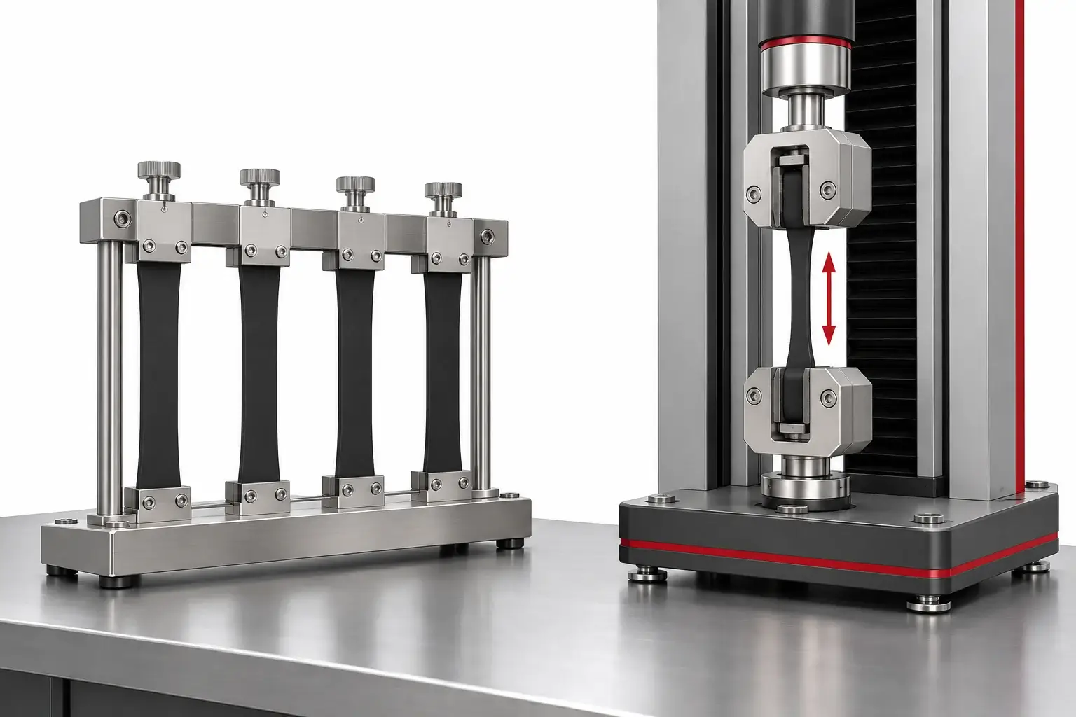
Choose the Deformation Condition Before the Fixture
Static exposure holds the specimen at a defined extension. Dynamic exposure varies the deformation according to a defined cycle. The appropriate arrangement follows the adopted method and the purpose of the evaluation; it should not be selected simply because one fixture looks more advanced.
ISO 1431-1 covers static and dynamic strain testing for ozone cracking of vulcanized or thermoplastic rubber. Obtain the controlled procedure used by the laboratory and identify its specimen, exposure and assessment requirements before finalizing the fixture.
A laboratory may compare compounds, verify a customer specification or examine a known failure in a formed part. Those tasks can require different specimen preparation and supports. Keep a comparative material test separate from a demonstration on a complete seal, hose or assembly.
Understand What Static and Dynamic Fixtures Must Do
| cURL Too many subrequests by single Worker invocation. To configure this limit, refer to https://developers.cloudflare.com/workers/wrangler/configuration/#limits | Static arrangement | Dynamic arrangement |
|---|---|---|
| Primary function | Maintain the specified extension during exposure | Apply the required changing deformation |
| Key inputs | Gauge length, extension, grip and specimen geometry | Initial/maximum strain, motion profile, frequency and grip geometry |
| Mechanical review | Grip security, alignment and extension adjustment | Travel, alignment, motion repeatability and cable/drive integration |
| Observation | Access to the required exposed and strained surface | Access and any specified stopped/strained observation condition |
| Capacity question | How many correctly mounted specimens fit with suitable spacing? | How many stations can operate under the required motion and loading? |
A rotating carrier and a dynamically stretching fixture are not the same function. Carrier rotation may move specimens through the chamber environment without changing their extension. Dynamic strain requires the specified change in specimen deformation.
Ask for a fixture drawing or demonstration that shows the actual motion. Describe whether all stations move together and what limits apply to the proposed specimen shape and quantity.
Define Strain Using the Correct Reference Length
For a simple uniaxial engineering-strain calculation, strain is the change in gauge length divided by the original gauge length. The reference points and measurement method must follow the adopted procedure. Do not automatically substitute overall specimen length or grip spacing for gauge length.
Formed seals, curved profiles and hoses may not behave like flat strips. Bending, compression and nonuniform extension can concentrate strain in particular areas. If a custom support is needed, provide the specimen drawing and the intended installed condition rather than asking for a generic percentage alone.
Define the material condition and preparation history as required by the method. A fixture cannot compensate for inconsistent specimens, unclear exposed surfaces or an undocumented strain reference.
Plan the Loaded Rack and Observation Access
Nominal chamber volume is not the number of usable test stations. Include the complete fixture, drive arrangement and any moving envelope. Check that specimens do not contact one another, the chamber wall or another part of the fixture during the full cycle.
Arrange the load to remain compatible with the method’s exposure requirements and the chamber circulation. Excessive loading or a large support can obstruct flow and make different positions less comparable. Use the agreed loading plan for both the trial and the routine test.
- Identify every specimen station and its strain setting.
- Show the exposed face and the area used for crack evaluation.
- Allow access for the required inspection without improvising the procedure.
- Record whether removal and remounting are allowed and how repeatability is maintained.
- Keep the specimen support and contact surfaces suitable for the exposure.
Where observations interrupt exposure, follow the specified timing and safety procedure. Do not open a chamber containing ozone simply to obtain a photograph. Gas handling, exhaust/destruction arrangements and access controls belong in the equipment and laboratory safety plan.
Send a Fixture Specification, Not Only a Chamber Volume
A useful inquiry includes the specimen drawing, material type, dimensions, required quantity, gauge/strain definition and whether motion is required. Add the adopted method, ozone and temperature conditions, exposure duration and evaluation procedure.
| Fixture request | Information to provide |
|---|---|
| Flat strips | Geometry, gauge reference, grip region and required extension |
| Seals or profiles | Cross-section, installed shape, support and evaluation surface |
| Hoses or curved parts | Diameter, bend/support arrangement and local observation area |
| Dynamic exposure | Strain range, cycle profile, frequency, quantity and moving envelope |
| Evidence package | Setting verification, specimen identification and inspection record |
Identify whether the fixture is included, interchangeable or project-specific. Separate the chamber’s environmental control from its specimen-deformation capability. Concentration control and tensile motion need their own agreed checks.
Demonstrate the Fixture with the Intended Specimen
Before routine exposure, demonstrate mounting and motion with the proposed sample or an agreed representative specimen. Check alignment, grip retention, setting reproducibility and the full movement envelope. Use suitable dimensional or motion measurements for the required tolerance.
Agree how strain settings and station identities will be recorded and how cracks will be observed and assessed. A fixture trial confirms mechanical suitability; it does not establish the rubber’s ozone resistance before the exposure and evaluation are completed.
ال DERUI ozone aging chamber page covers the equipment family. Use the acceptance record template to link the ordered fixture, its demonstration and the environmental checks. Submit sample drawings when requesting a configuration review so usable capacity and fixture scope can be defined together.
Distinguish Motion Settings from Strain at the Specimen
A drive stroke or grip displacement is not automatically the strain applied to the evaluation region. Grip slip, fixture compliance and specimen geometry can change the relationship. Define the gauge reference and verify the setting using the adopted method.
In a hypothetical comparison, two fixtures can move through the same distance while holding specimens with different initial gauge lengths. Their engineering strains will differ. The useful purchase requirement therefore includes the specimen reference length and deformation condition, not only motor travel.
For a dynamic arrangement, record the relationship between commanded motion and the specimen cycle. Ask how frequency, travel and repeatability will be checked with the proposed sample. A moving demonstration without a mounted specimen can show mechanical motion, but not the complete deformation condition used for the rubber test.
Control the Specimen Arrangement During Comparative Tests
When comparing compounds, use consistent preparation, mounting and observation procedures within the adopted method. Identify the exposed and evaluated surfaces so fixture contact does not hide or alter the region of interest.
Record station numbers and settings before exposure. If the test permits inspection or remounting, document how those actions are performed consistently. A changed grip position or an undocumented adjustment can make the next observation difficult to compare with the previous one.
Do not describe a finished hose or seal test as equivalent to a standard strip test simply because the nominal strain is the same. The part geometry and intended question differ. Ask whether the project needs material comparison, an application-specific part assessment or both, and keep the corresponding evidence separate.
Review a Fixture Proposal Without Overbuying Motion
Compare fixture proposals against the required deformation and number of usable stations. An extra drive function has little value if the laboratory only needs a controlled static exposure. Conversely, carrier rotation cannot substitute for a specified dynamic tensile cycle.
Check the quoted accessories: grips, supports, adjustment tools, specimen identification and any interchangeable assemblies. Identify the environmental conditions and samples represented by the mechanical demonstration. Do not extend a strip-fixture result to every custom part.
The final selection record should connect the adopted procedure, specimen drawing, strain definition, station layout and observation method. Supply that record with the ozone chamber enquiry so environmental control, fixture capacity and safe operation are reviewed as related but distinct requirements.
Questions Before You Specify the Equipment
Does specimen-rack rotation mean dynamic strain testing?
No. Rotation can move a specimen without changing its extension. Dynamic strain requires the prescribed changing deformation at the specimen.
Is 20% strain required for every rubber ozone test?
No. Use the strain condition required by the adopted method and application. The calculation in this article is only an arithmetic example.
Can a standard strip fixture hold a finished rubber seal?
Not necessarily. A formed seal may need supports that reproduce the required deformation without hiding the evaluation surface or introducing unintended stress.
How should fixture capacity be stated?
State the number and geometry of specimens that can be mounted and operated at the required settings, with the agreed spacing and observation access—not chamber liters alone.
Review My Rubber Specimen Fixture
Send the rubber specimen drawing, quantity, strain requirement and static or dynamic cycle. Ask DERUI to align the fixture, chamber loading and acceptance demonstration with your test.