VOC Emission Chamber Loading Factor: Specimen Area and Airflow Planning
Ngày phát hành:11/09/2026 Phân loại:Resources、Bài viết kỹ thuật Lượt xem:9041
A VOC chamber can physically accommodate a specimen and still be unsuitable for the required loading factor. Start with the adopted test method, exposed surface definition, chamber volume and airflow. Keeping these inputs separate helps the laboratory select a useful specimen size and specify the right equipment and sampling arrangement.
Confirm Which Loading Definition the Method Uses
This article explains an area-based loading factor for material-emission chamber planning. It is not a universal definition for every product or method. Some programmes define loading by product type, count, length or another basis; use the definition required by the laboratory’s controlled procedure.
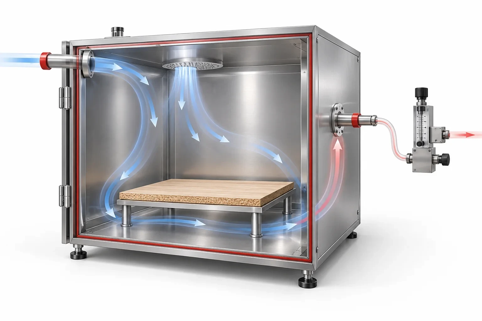
For an area-based case, the loading factor L is the exposed specimen area A divided by chamber volume V. If A is in square meters and V is in cubic meters, L is expressed in m²/m³. Record both input values rather than reporting the ratio alone.
The physical dimensions of a sample are not always the exposed area. A coated panel may expose one face, both faces, selected edges or a specified combination. Preparation, edge treatment, storage and conditioning need to follow the applicable method because they affect the emission task being measured.
Calculate Area, Volume and Air Changes with Consistent Units
| Số lượng | Relationship | Units used here |
|---|---|---|
| Area-based loading factor | L = A ÷ V | m²/m³ |
| Air change rate | n = Q ÷ V | h⁻¹ when Q is m³/h |
| Area-specific ventilation | qA = Q ÷ A = n ÷ L | m³/(m²·h), equivalent to m/h |
Here Q is the applicable chamber ventilation flow under the method’s stated reference conditions. It is not an internal circulation fan rating. Internal air movement and ventilation through the chamber serve different roles and should not be substituted for one another.
Check conversions before sizing the airflow system. For example, 50 liters per hour is 0.050 m³/h. A flow stated per minute must be converted to the same time basis used in the air-change calculation. Where a flow is referenced to standard conditions, document the reference and use the procedure’s required correction basis.
The equations describe input relationships. They do not set a permitted loading factor, a material-emission limit or a chamber’s achievable measurement accuracy.
Work Through Two Hypothetical Loading Cases
Consider a hypothetical flat specimen with one exposed face measuring 0.50 × 0.40 m. Its exposed area is 0.20 m². Assume the procedure accepts the stated preparation and all other surfaces are treated as required. Place it in an assumed 0.10 m³ chamber with a ventilation flow of 0.050 m³/h.
| Planning input or result | Case A: one exposed face | Case B: doubled exposed area |
|---|---|---|
| Exposed area A | 0.20 m² | 0.40 m² |
| Chamber volume V | 0.10 m³ | 0.10 m³ |
| Ventilation Q | 0.050 m³/h | 0.050 m³/h |
| Loading factor L | 2.0 m²/m³ | 4.0 m²/m³ |
| Air change rate n | 0.50 h⁻¹ | 0.50 h⁻¹ |
| Area-specific ventilation qA | 0.25 m/h | 0.125 m/h |
These are arithmetic examples, not a prescribed test condition or DERUI product performance. Doubling exposed area while keeping chamber volume and ventilation unchanged doubles loading factor and halves area-specific ventilation. It does not justify assuming that concentration or emission rate will change by a fixed proportion.
If the method requires a particular area-specific ventilation, changing sample area may require changing the flow as well. Check whether the selected chamber and flow-control system can support the required combination with the relevant tolerance.
Distinguish Concentration from Emission Rate
A measured chamber-air concentration and a material’s emission rate answer different questions. Concentration depends on the test setup as well as on the material. Ventilation, loading, sample age, temperature, humidity and the sampling time are part of that setup.
Do not compare two concentration results as though only the material changed when their loading factors or airflow differ. Likewise, do not present a chamber concentration as the concentration in an occupied room without an appropriate exposure model and the required assumptions.
The analytical result comes from the specified sampling and laboratory analysis, not from the climate chamber alone. Identify target compounds, sampling media, collection flow, analytical procedure and reporting basis in the test plan. A chamber display of temperature and humidity is not a VOC measurement.
Blank/background checks, recovery assessment and other quality controls help establish whether the chamber system is suitable for the intended analysis. Their criteria belong to the adopted method and project requirements, not a generic equipment brochure.
Select the Chamber Around the Complete Measurement System
Geometric fit is only the first check. Include specimen supports, air distribution, sampling ports, clean-air preparation and access for cleaning or conditioning. Materials, seals and internal surfaces must be appropriate for the background and recovery requirements of the method.
| RFQ input | cURL Too many subrequests by single Worker invocation. To configure this limit, refer to https://developers.cloudflare.com/workers/wrangler/configuration/#limits |
|---|---|
| Method and specimen | Controlled procedure, material type, preparation and exposed-area definition |
| Geometry | Specimen dimensions, support and required chamber volume |
| Climate and flow | Temperature, RH, ventilation, air movement and applicable tolerances |
| Analysis and sampling | Target compounds, ports, media, sampling flows and schedule |
| Quality control | Background, recovery, cleaning and records required |
| Supply boundary | Chamber, clean-air unit, flow control, sampling equipment and external analysis |
A one-cubic-meter chamber is not automatically appropriate for every building material or complete furnishing. Select volume from the actual specimen, the method’s loading basis and the complete system performance.
Document the Assumptions Before Requesting a Proposal
Prepare a one-page loading record containing area calculation, chamber volume, flow, units, specimen history and surface treatment. Identify which values are prescribed by the method and which are the laboratory’s design choices. Resolve inconsistent units before comparing equipment.
The DERUI VOC test chamber page describes the equipment family. Use the acceptance record structure to organize agreed chamber-system checks, while retaining the VOC method’s own verification and analytical requirements.
For a configuration review, provide the material method, specimen dimensions, exposed area, desired loading basis, environmental conditions and sampling arrangement. This allows the chamber, clean-air supply and flow-control scope to be reviewed together rather than as unrelated accessories.
Check a Loading Calculation Before Choosing a Chamber
Reconstruct the exposed area from the specimen drawing. Mark each face and edge that the adopted method includes, and identify surfaces sealed or excluded. Keep this marked drawing with the numerical calculation rather than relying on a remembered nominal panel size.
Then convert chamber volume and ventilation flow into consistent units. Report the selected reference conditions for flow where the method requires them. A correct arithmetic result can still be inappropriate if its area definition or airflow basis does not match the procedure.
Have another reviewer reproduce the calculation from the recorded inputs. This is especially useful when a specimen is cut to fit a smaller chamber or several pieces represent one product. The question is not merely whether the pieces fit, but whether the resulting loading and preparation still represent the specified test.
Evaluate a Change in Specimen Quantity Before Running It
Adding specimens changes exposed area and therefore the area-based loading factor when volume stays fixed. If ventilation is unchanged, area-specific ventilation changes too. Decide whether that new combination is allowed by the adopted procedure before treating it as a higher-capacity version of the same test.
For the hypothetical cases above, the numerical relationships can be calculated exactly from the stated inputs. The resulting concentration cannot be predicted by a universal multiplier because material behaviour, time and chamber interactions also matter.
Prepare a change note stating the new area, flow, loading factor, preparation and sampling plan. If the programme uses a modelled reference environment, review its assumptions as well. This creates a defensible basis for comparing results and avoids explaining different concentrations as material changes when the test setup also changed.
Keep Chamber Supply and Analytical Capability Separate
A climate-controlled enclosure is only one part of an emission measurement system. Identify clean-air preparation, flow measurement, sampling equipment, analytical services and quality-control responsibilities alongside chamber construction.
Ask which parts of the background and recovery demonstration are included in equipment acceptance and which require the laboratory's analytical method. Name the compounds or analytical scope where relevant. A general temperature-uniformity report cannot establish low background or recovery for every target substance.
For an enquiry, provide the method, surface calculation, sample history, desired volume and ventilation, sampling schedule and analytical boundary. A proposal based on those inputs can be compared on the intended measurement task, rather than on litres or stainless-steel construction alone.
Questions Before You Specify the Equipment
Is loading factor the specimen volume divided by chamber volume?
Not for the area-based definition used here. It is exposed specimen area divided by chamber volume. Other methods may use different definitions; follow the adopted procedure.
Can I use both faces of a panel in the area calculation?
Only if the method and specimen preparation define both faces as exposed. Document surfaces and edge treatment rather than assuming that all physical area counts.
Does internal fan flow determine air changes per hour?
No. Air changes use the relevant chamber ventilation flow divided by volume. Internal circulation is a separate parameter.
Does doubling the specimen area double the measured VOC concentration?
Do not assume a universal proportional result. The material’s emission behavior, ventilation, time and chamber interactions must be considered under the applicable method.
Review My VOC Chamber Loading Plan
Send the method, material dimensions, exposed area, ventilation and sampling requirements. Ask DERUI to align chamber volume, climate control and the supplied air/sampling interfaces with your laboratory plan.