Adding a Climatic Chamber to an Existing Shaker: An Interface Checklist
Дата публикации:11/09/2026 Категория:Resources、Технические статьи Просмотры:4744
Adding temperature or humidity to an existing vibration system is an integration project, not simply placing a box above the shaker. Mechanical alignment, moving clearance, thermal isolation, sealing and control responsibilities determine whether the combined setup can perform the required test. Begin with the installed shaker and specimen drawings.
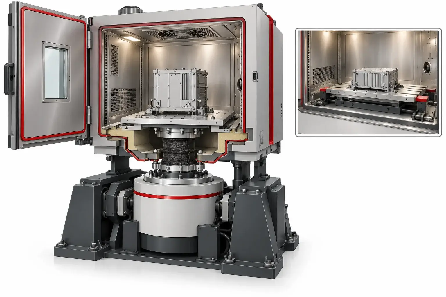
Identify the Complete Existing Vibration System
Record the shaker manufacturer, exact equipment identity, controller, amplifier and available accessories. Include armature or head-expander geometry and any horizontal slip table. Keep these records with the current installation drawings so the interface review is based on the system actually in service.
Provide the vibration duty for the complete payload: specimen, fixture, adapters and any moving interface components. A headline force rating is not enough to approve a proposed test. The required spectrum, frequency range, displacement, velocity, acceleration and operating restrictions need to be evaluated by the responsible vibration-system engineer.
Identify whether the laboratory needs vertical testing, horizontal testing or both, and whether the chamber must be moved between positions. A system that fits one orientation may need a different base opening, support or alignment arrangement for the other.
Develop the Interface from the Moving Envelope
Measure the shaker/table working height and define the full moving envelope. Include the specimen and fixture at maximum displacement, cable movement and any accessible service positions. Do not approve an interface using static fit alone.
The chamber support and shaker motion have different roles. Review how the chamber is supported, how alignment is set and which components move with the vibration system. An unreviewed contact between a moving table and a chamber structure can invalidate the setup or damage equipment.
| Interface item | cURL Too many subrequests by single Worker invocation. To configure this limit, refer to https://developers.cloudflare.com/workers/wrangler/configuration/#limits | Question to resolve |
|---|---|---|
| Vertical connection | Armature/head-expander drawing, height and travel | Can the proposed base interface accommodate the full motion? |
| Horizontal connection | Slip-table envelope, axes, fixture and access | Does the chamber opening and seal suit the required movement? |
| Fixture | Bolt pattern, geometry, mass and specimen position | Is the complete assembly within the reviewed mechanical duty? |
| Поддержка | Chamber base, floor and positioning arrangement | Are structural load paths and alignment responsibilities defined? |
| Access | Loading, lifting, fastening and service clearances | Can operators set up the test without an improvised method? |
Use approved interface drawings from both sides of the integration. Do not drill, alter a load-bearing component or modify the shaker without the relevant manufacturer’s engineering approval.
Separate Thermal Isolation from Mechanical Attachment
A combined system must maintain a useful environmental boundary while allowing the required mechanical motion. The interface may involve insulation, a flexible seal, an extension or another engineered arrangement. Its design must account for temperature, movement, durability and access.
Heat can travel through the fixture and interface into parts that were not intended to experience the chamber temperature. Identify temperature restrictions for the shaker, bearings, slip table, cables and other components. Discuss how those limits will be monitored or protected.
Humidity introduces additional questions around condensation, leakage and exposed equipment below the chamber. Review the valid temperature–humidity operating points with the complete interface and specimen. A sealed-looking base does not by itself establish suitability for all humidity conditions.
Do not assume the chamber’s stand-alone environmental performance remains unchanged after adding an interface opening and a vibrating load. Define the combined operating conditions that the system is expected to demonstrate.
Include Specimen Services and Control Responsibilities
Powered specimens may need electrical, coolant, communication and measurement connections. Provide cable and hose counts, sizes, bend limits, motion and heat output. Route these services so they do not unintentionally restrain the specimen, interfere with the shaker or compromise the environmental seal.
List the functions that require coordination between the chamber and vibration controller. A project may need a common start condition, a status permissive, a stop request or synchronized records. Define the intended behavior rather than assuming a generic communication connector provides it.
| Responsibility | What to agree |
|---|---|
| Mechanical interface | Design owner, drawings, fabrication and alignment checks |
| Environmental boundary | Seal/insulation scope and the conditions to be demonstrated |
| Vibration control | Controller setup, fixture assessment and vibration acceptance |
| Coordination and protection | Required signals, responses and authorized functional tests |
| Data and handover | Time alignment, records, manuals and operator training |
Protection and fault-response requirements should be developed by qualified personnel for the installed system. Do not bypass an interlock to make two independent pieces of equipment run together.
Request Evidence for the Combined Test Duty
Begin with a documented setup check and the authorized commissioning sequence. Review mechanical fit and motion, environmental operation and the agreed combined duty. Identify the specimen/representative load and fixture used for each result.
A chamber report with a closed base and no shaker connection does not demonstrate the installed interface. A shaker demonstration at room temperature does not establish the complete climatic-vibration duty. Retain both component evidence and the agreed combined-system records.
Record chamber-air and relevant specimen temperatures, environmental conditions, vibration control/response information and the timing basis requested by the test plan. Identify any interrupted runs or changed fixture settings.
The FAT record template can organize requirements and evidence, but the combined system needs its own approved integration and acceptance procedure. Use the laboratory’s adopted vibration and environmental methods to establish the detailed limits.
Build the Integration Inquiry Around Drawings
Send the existing shaker, head-expander/slip-table and laboratory layout drawings together with specimen and fixture information. Include environmental profiles, vibration duty, required axes, services and restrictions on moving the installed equipment.
Ask for a written scope identifying what is supplied, what remains with the existing system and who approves each interface. Confirm whether the chamber can also be used independently and which floor/base components are supplied for that mode.
The vibration climatic test chamber page covers the equipment family, while the cURL Too many subrequests by single Worker invocation. To configure this limit, refer to https://developers.cloudflare.com/workers/wrangler/configuration/#limits helps distinguish other integrated fixtures and test functions. For an existing shaker, compatibility is assessed from the exact configuration; it is not guaranteed by brand or nominal chamber volume.
Use an Interface Freeze Before Manufacturing
Bring the chamber supplier, existing shaker owner and fixture engineer into one interface review. Agree which drawing defines the working height, opening, support, mounting pattern and movement envelope. Record the revision accepted by each responsible party.
Freeze the interface only after loading and service access have been considered. A geometrically compatible base can still make fixture fastening or sensor connection impractical. Include the tools and handling space used during real setup.
If the specimen or fixture changes afterwards, assess the mechanical and thermal implications before accepting the new arrangement. A small adapter can add mass, alter alignment or conduct heat into protected components. Do not let an undocumented workshop modification become the assumed basis for the combined-system demonstration.
Compare Retrofit Scope with Replacement or Separate Testing
Retrofitting may preserve a useful shaker, but the comparison needs more than chamber price. Include interface engineering, any shaker-approved modifications, installation downtime, positioning equipment and the evidence required to accept the combined duty.
Ask whether the existing system's condition and available documentation support the proposed integration. Missing drawings or restricted access may add survey work. These are project constraints, not proof that the existing system cannot be used.
Where a test programme permits separate exposures, evaluate that route with the responsible laboratory rather than assuming simultaneous testing is always necessary. Where simultaneous climate and vibration is required, separate component tests cannot be presented as equivalent evidence. The approved programme determines the equipment task.
Record Combined-System Limitations at Handover
List the reviewed fixture, payload, axes, motion and environmental operating conditions with the final interface drawing. Identify which component limits govern the installation and where those limits are documented.
Include the procedure for moving or reconfiguring the chamber if more than one orientation is supplied. Operators need an approved setup method and a clear identification of the correct seals, floor elements and support positions for each mode.
For future projects, compare the new specimen and fixture with that accepted envelope before running them. This is more useful than a broad statement that the chamber fits a particular shaker brand. Send the actual configuration with an enquiry so compatibility is assessed on drawings and duty, not assumed from names.
Questions Before You Specify the Equipment
Can a climatic chamber fit any existing shaker?
Compatibility requires an engineering review of the installed geometry, moving envelope, duty, temperature limits, seals and controls. Do not assume universal fit.
Can the same chamber cover vertical and horizontal vibration?
It may be possible with an appropriate interface and positioning arrangement. Provide both configurations and their full movement and loading details for review.
Is a room-temperature shaker report enough for combined testing?
No. It describes that tested condition. Define the evidence needed for the integrated environmental and vibration duty with the intended interface and load.
What drawings should I send first?
Provide shaker/head-expander or slip-table drawings, working height, travel, fixture and specimen drawings, chamber location and required environmental/vibration profiles.
Review My Existing Shaker Interface
Send the shaker and fixture drawings, working height, motion requirements and climate profile. Ask DERUI to review the mechanical interface, environmental boundary and integration scope.